In a series C–R circuit, applied voltage is volt. What is the (i) The peak voltage (ii) Average voltage over half cycle ?
(i) Volt
(ii) volt.
Topper's Solved these Questions
- UNIT–III & UNIT–IV MAGNETIC EFFECTS OF CURRENT AND MAGNETISM & E.M.I. AND ALTERNATING CURRENTBook:CBSE COMPLEMENTARY MATERIALChapter:UNIT–III & UNIT–IV MAGNETIC EFFECTS OF CURRENT AND MAGNETISM & E.M.I. AND ALTERNATING CURRENTExercise:LONG ANSWER QUESTIONS (5 Marks)
Explore 5 Videos
- SAMPLE QUESTION PAPER 2019Book:CBSE COMPLEMENTARY MATERIALChapter:SAMPLE QUESTION PAPER 2019Exercise:Section C
Explore 19 Videos
Similar Questions
Knowledge Check
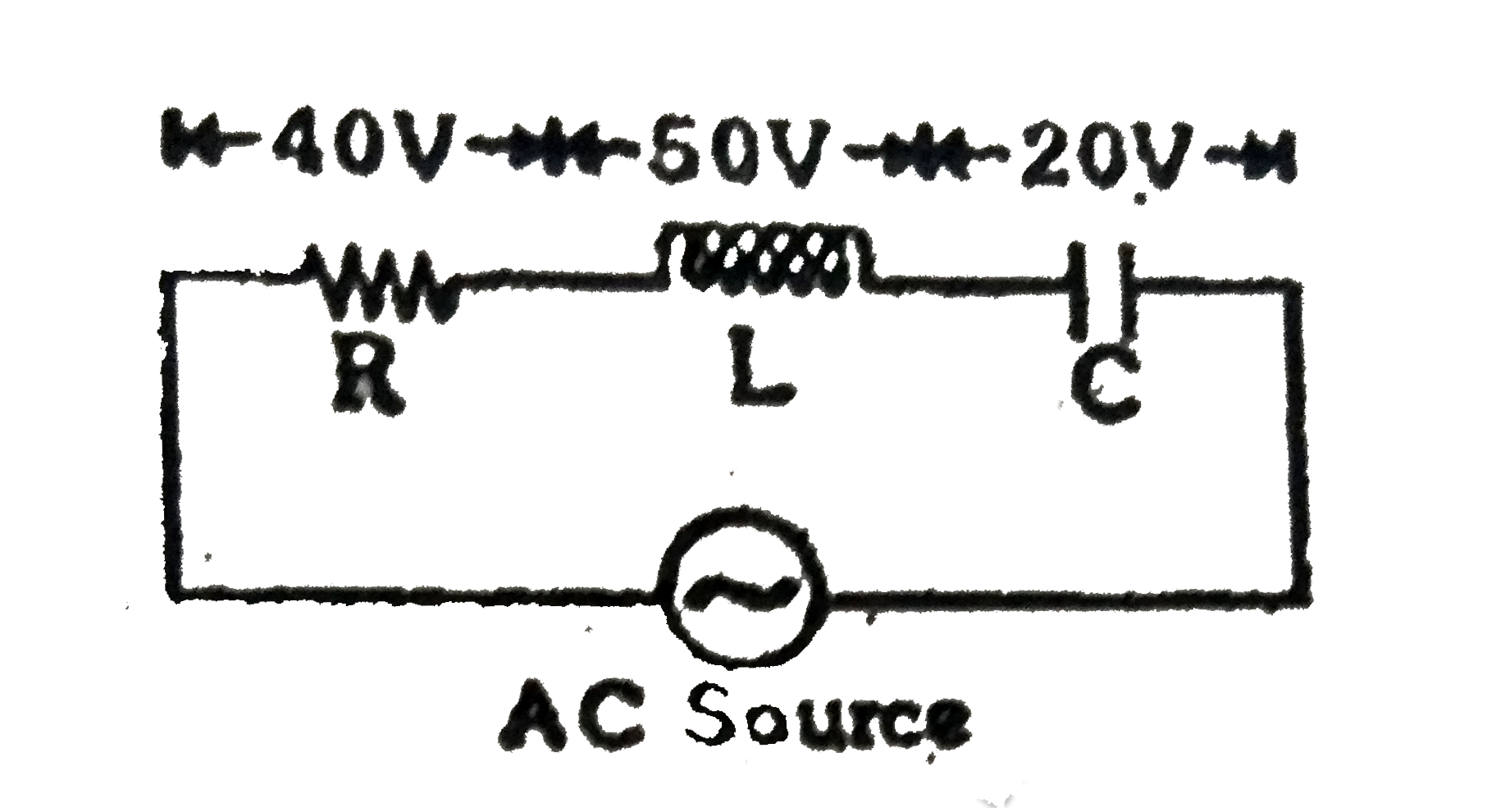
In series LCR circuit, the voltages across R, L and C are shown in the figure. The voltage of applied source
 A110 VB10 voltC50 voltD70 volt
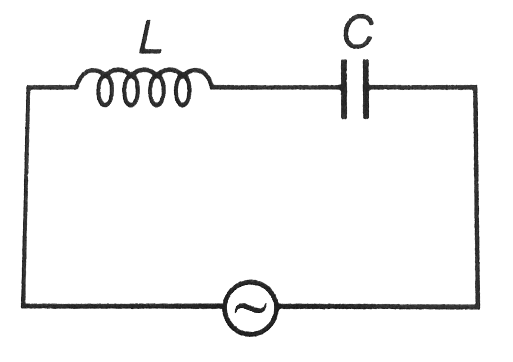
In a series L−C circuit, the applied voltage is V0. if omega is very low, then the voltage drop across the inductor VL and capacitor VC are
 .AVL=V02,VC=V02BVL=0,VC=V0CVL=V0,VC=0DVL=−VC=V02
In an AC circuit, peak value of voltage is 423 volts. Its effective voltage is
A400 voltsB323 voltsC300 voltsD340 volts
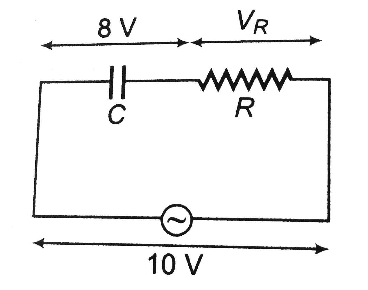
In a series CR circuit shown in figure,the applied voltage is 10V and the voltage across capacitor is found to be 8V
View SolutionIn an a.c. circuit, the rms voltage is 100√2V. Find the peak value of voltage and its means value during a positve half cycle.
View SolutionIn a series C−R circuit shown in figureure, the applied voltage is 10V and the voltage across capacitor is found to8V. The voltage across R, and the phase difference between current and the applied voltage will respectively be
 .
.
View SolutionIn a series C−R circuit shown in figureure, the applied voltage is 10V and the voltage across capacitor is found to8V. The voltage across R, and the phase difference between current and the applied voltage will respectively be
 .
.
View SolutionAn alternating voltage is represented by
V=80sin(100πt)cos(100πt) volt,
What is the peak voltage?
View Solution
