In a series C−R circuit shown in figureure, the applied voltage is 10V and the voltage across capacitor is found to8V. The voltage across R, and the phase difference between current and the applied voltage will respectively be
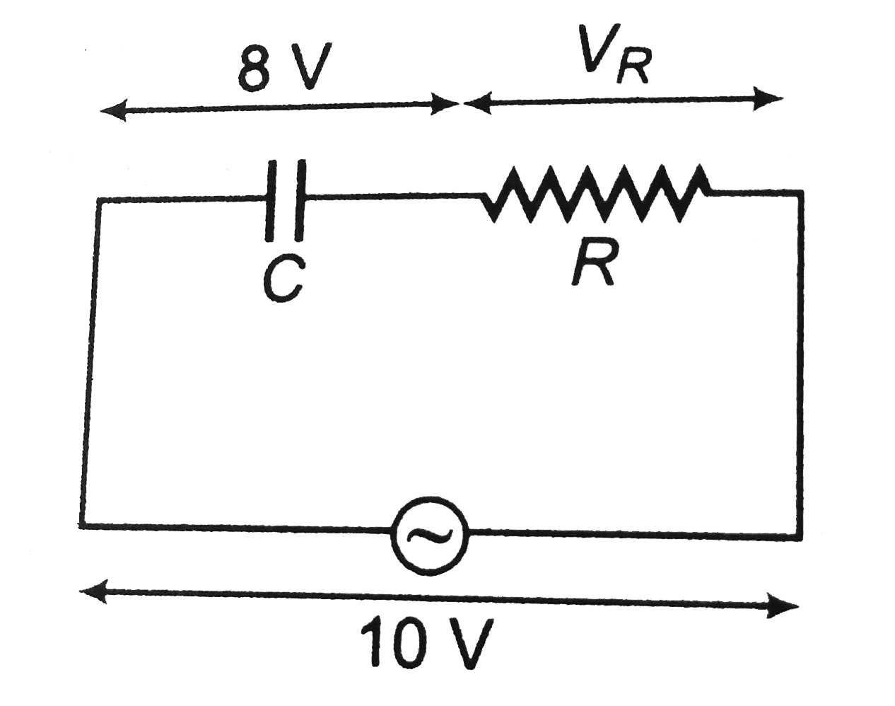 .
.
6V, tan−1(43)
3V,tan−1(34)
6V,tan−1(53)
None of these
The correct Answer is:A
We know that, for series R-C circuit
V2=V2C+V2R
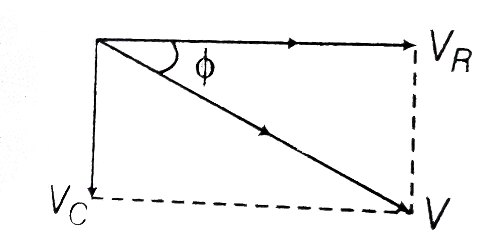
100=64+V2R=36⇒VR=√36=6V
Also, tanϕ=VCVR⇒tanϕ=86
tanϕ=43
∴ϕ=tan−1(43)
Topper's Solved these Questions
- SOLVED PAPERS 2018BOOK - DC PANDEY ENGLISHCHAPTER - SOLVED PAPERS 2018EXERCISE - Assertion and Reasons
10 Videos
- SOLVED PAPERS 2018BOOK - DC PANDEY ENGLISHCHAPTER - SOLVED PAPERS 2018EXERCISE - JIPMER
22 Videos
- SOLVED PAPERS 2018BOOK - DC PANDEY ENGLISHCHAPTER - SOLVED PAPERS 2018EXERCISE - JIPMER
22 Videos
- SOLVED PAPER 2017BOOK - DC PANDEY ENGLISHCHAPTER - SOLVED PAPER 2017EXERCISE - Solved papers 2017(JIPMER)
32 Videos
- WAVE OPTICSBOOK - DC PANDEY ENGLISHCHAPTER - WAVE OPTICSEXERCISE - For JEE Advanced E. Integer Type Questions
13 Videos
Similar Questions
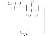
In the circuit shown in the figure, the total charge is 750μC and the voltage across capacitor C2 is 20 V. Then the charge on capacitor C2 is:
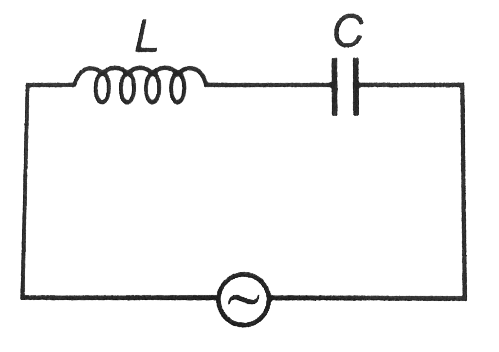
View SolutionThe phase difference between voltage and current in series L-C circuit is
View SolutionIn series LCR circuit, the phase difference between voltage across L and voltage across C is
View SolutionIn a series L−C circuit, the applied voltage is V0. if omega is very low, then the voltage drop across the inductor VL and capacitor VC are
 .
.
View SolutionIn a series L−C−R circuit, currenrt in the circuit is 11A when the applied voltage is 220V. voltage across the caspcitor is 200V. If the value of resistor is 20Ω, then the voltage across the unknown inductor is
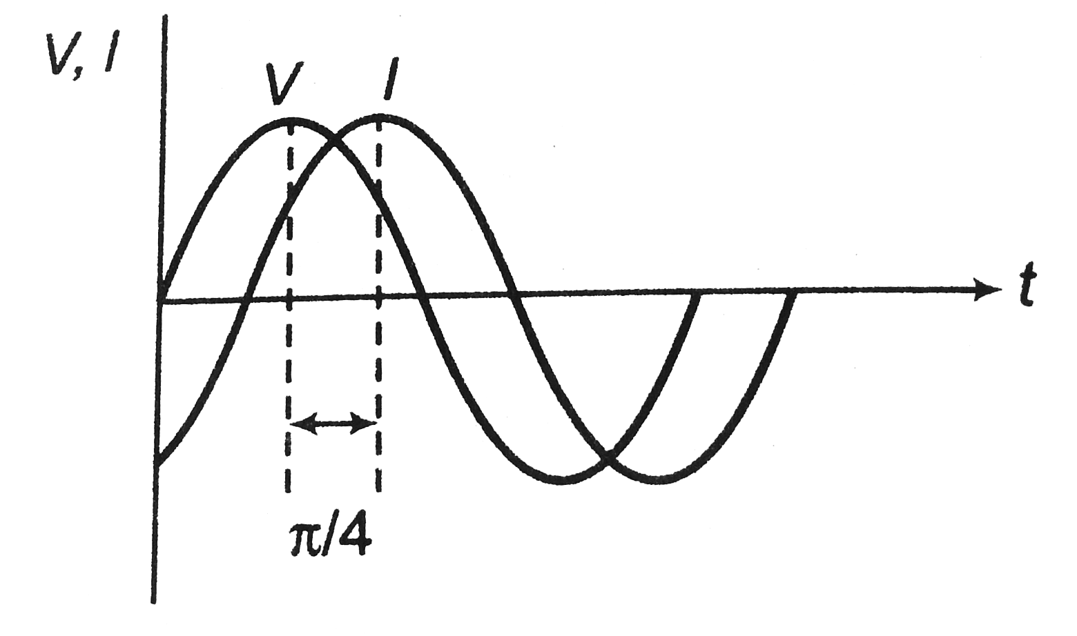
View SolutionAn Ac voltage V=V0sin100t is applied to the circuit, the phase difference between current and voltage is found to be π4, then
 .
.
View SolutionAn Ac voltage V=V0sin100t is applied to the circuit, the phase difference between current and voltage is found to be π4, then
 .
.
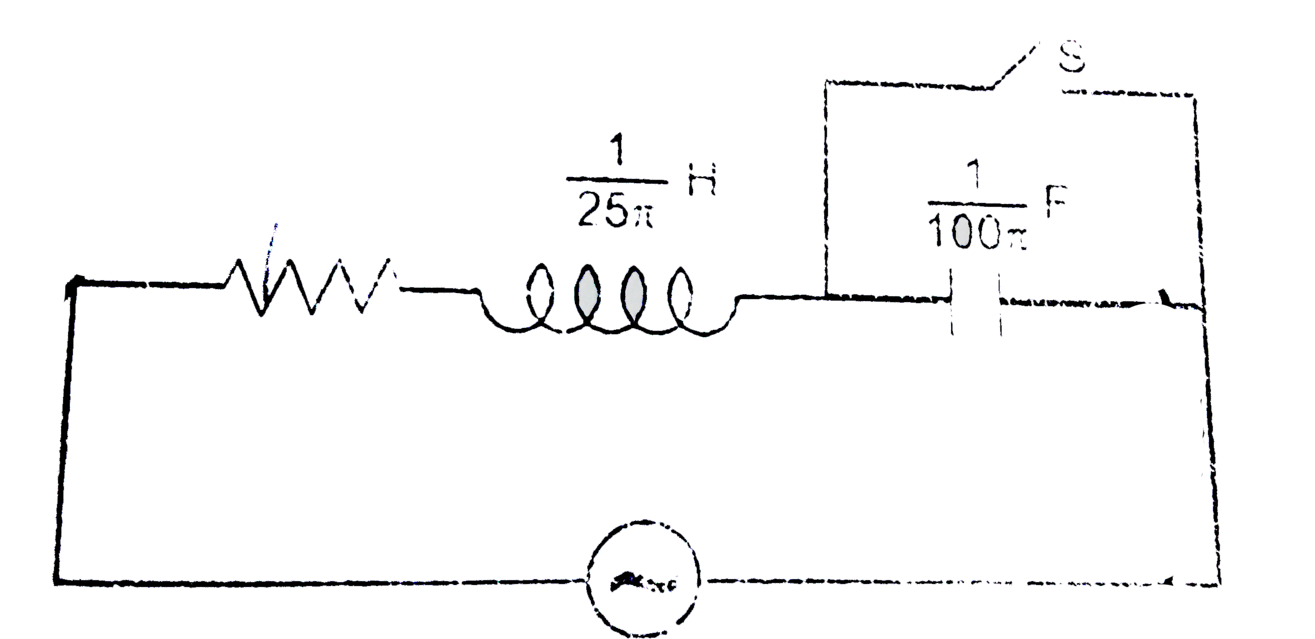
View SolutionIn the LCR circuit shown in figure unknown resistance and alternating voltage source are connected.When swith S is closed then there is a phase difference of π4 between current and applied voltage and voltage across resister is 100√2V.When switch is open current and applied voltage are in same phase.Neglecting resistance of connecting wire answer the following questions :
Peak voltage of applied voltage sources is:
View SolutionIn a series LCR circuit resistance R=10Ω and the impedance Z=10Ω The phase difference between the current and the voltage is
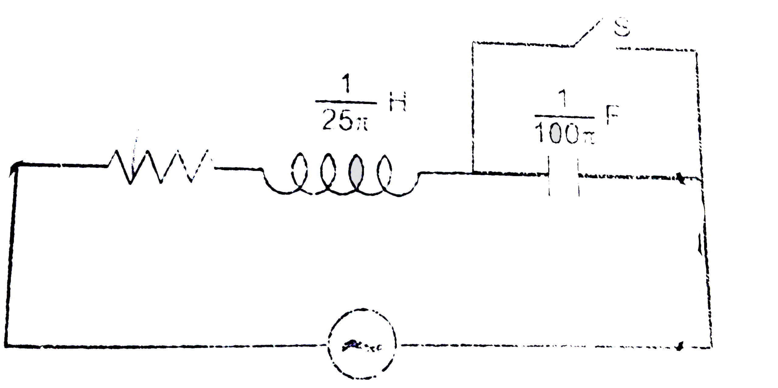
View SolutionIn the LCR circuit shown in figure unknown resistance and alternating voltage source are connected.When swith S is closed then there is a phase difference of π4 between current and applied voltage and voltage across resister is 100√2V.When switch is open current and applied voltage are in same phase.Neglecting resistance of connecting wire answer the following questions :
Resonance frequency of circuit is:
View Solution