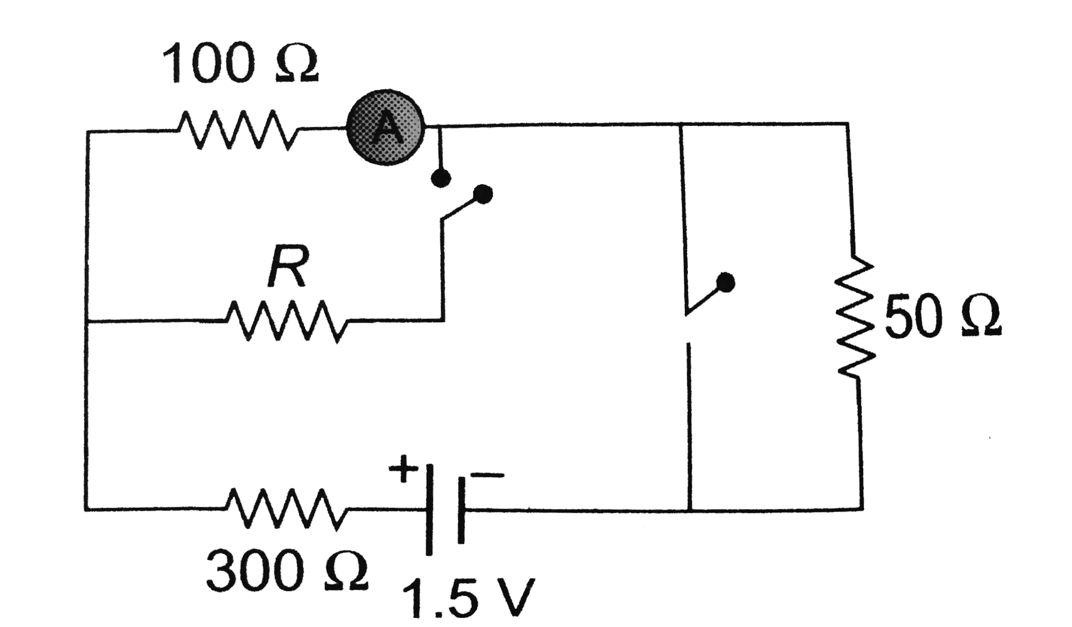
In the circuit as shown in figure , the reading of ammeter (ideal) in the same with both switches one and both switches closed. Find the resistance R ( in Ω)
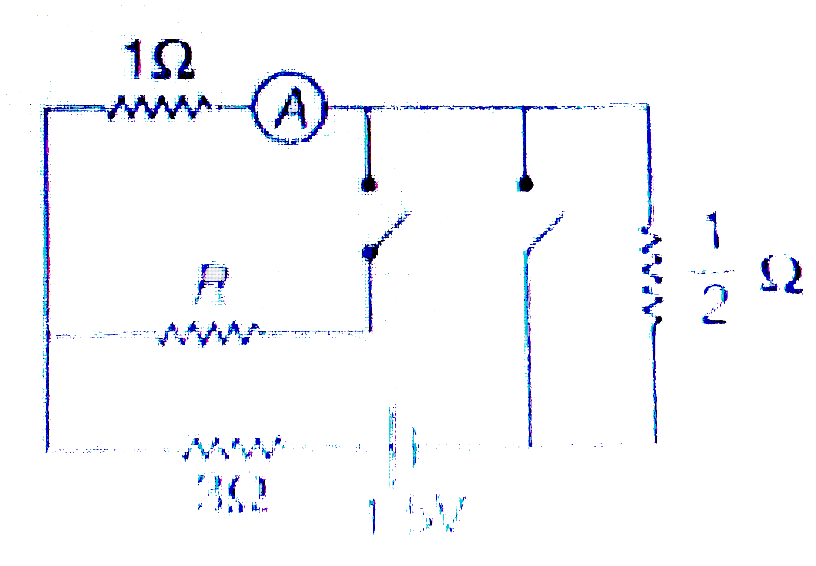
The correct Answer is:6
Step by step video, text & image solution for In the circuit as shown in figure , the reading of ammeter (ideal) in the same with both switches one and both switches closed. Find the resistance R ( in Omega) by Physics experts to help you in doubts & scoring excellent marks in Class 11 exams.
Updated on:21/07/2023Topper's Solved these Questions
Similar Questions
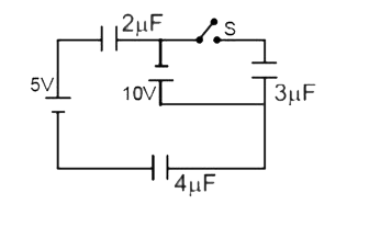
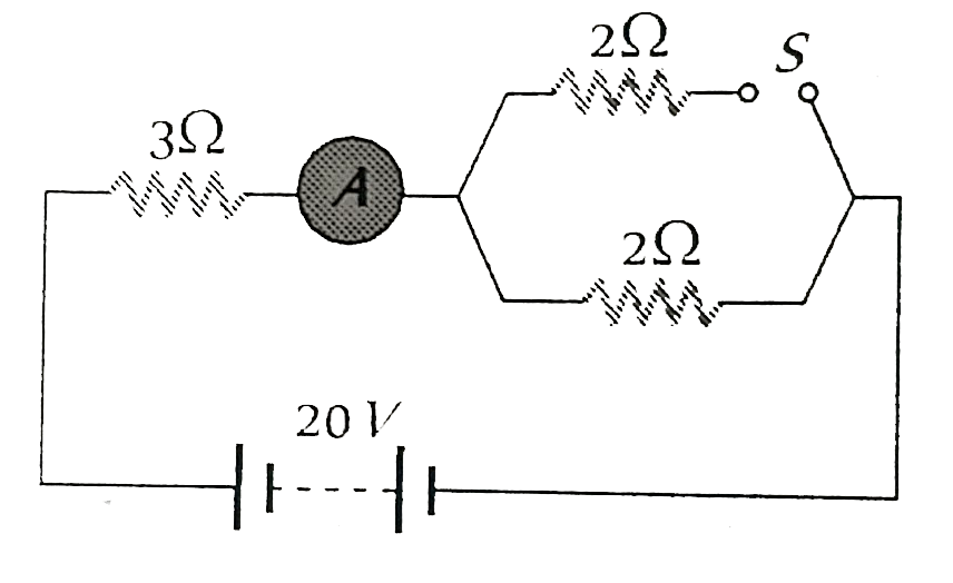
In the circuit shown in figure, find the amount of heat generated when switch s is closed.
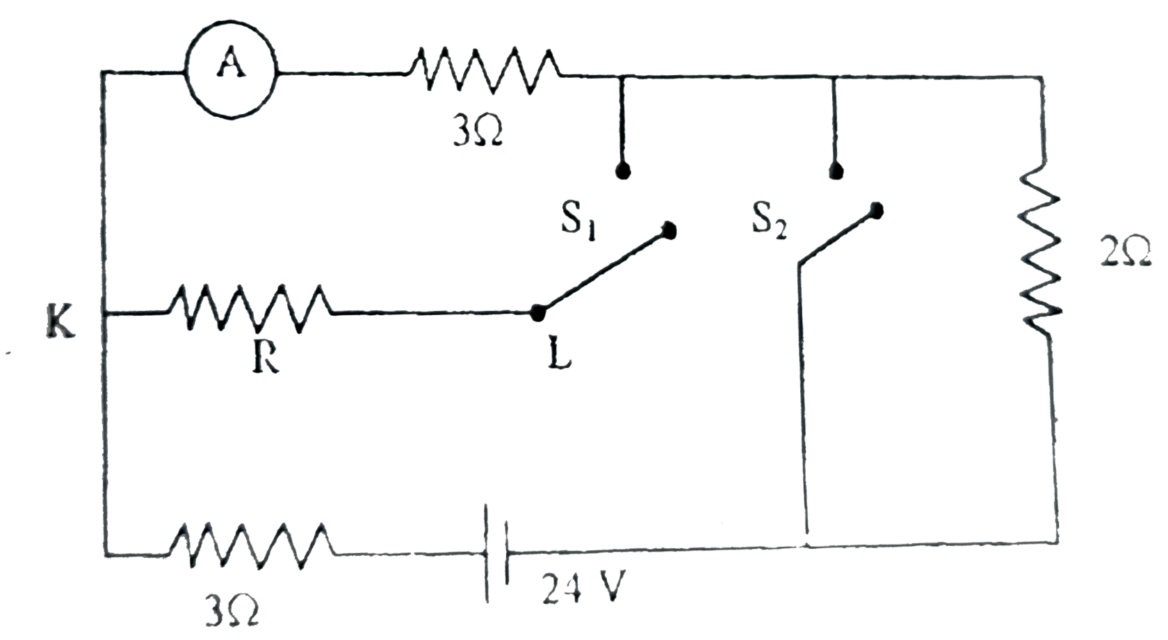
View SolutionIn the circuit shown in the figure, the ideal ammeter reading for current is taken
(a) with both switches open
(b) with both switches closed.
The readings are same in the cases. The value of resistance R is
View Solution
Knowledge Check
In the circuit shown in figure, reading of ammeter will
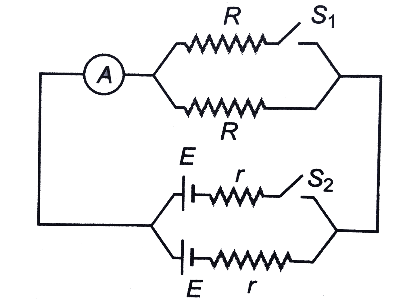 Ashows no deflection if S1 is closedBdecrease if S2 is closedCincrease if S2 is closedDdecrease if S2 is closed
In the circuit shown in figure the reading of ammeter is the same with both switches open as with both closed. Then find the resistance R. (ammeter is ideal).
 A550ΩB400ΩC350ΩD600Ω
In the circuit shown, the reading of the ammeter if diode is not ideal, will be
 A0B15mAC>15mAD<15mA
In the circuit P≠R, the reading of the galvanometer is same with switch S open or closed. Then
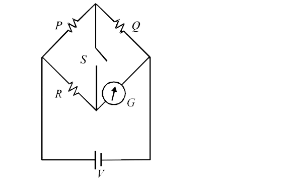
View SolutionIn the circuit shown P≠R the reading of galvonometer is same switch S open or closed. Then
View SolutionIn the circuit shown as P≠R and the reading of the galvanometer G is same with the switch open or closer. Then
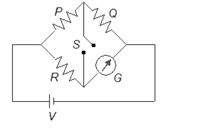
View SolutionIn the circuit shown, the reading of ammeter when switch S is open and when switch S is closed respectively are
View SolutionIn the circuit as shown in figure the switch is closed at t=0.
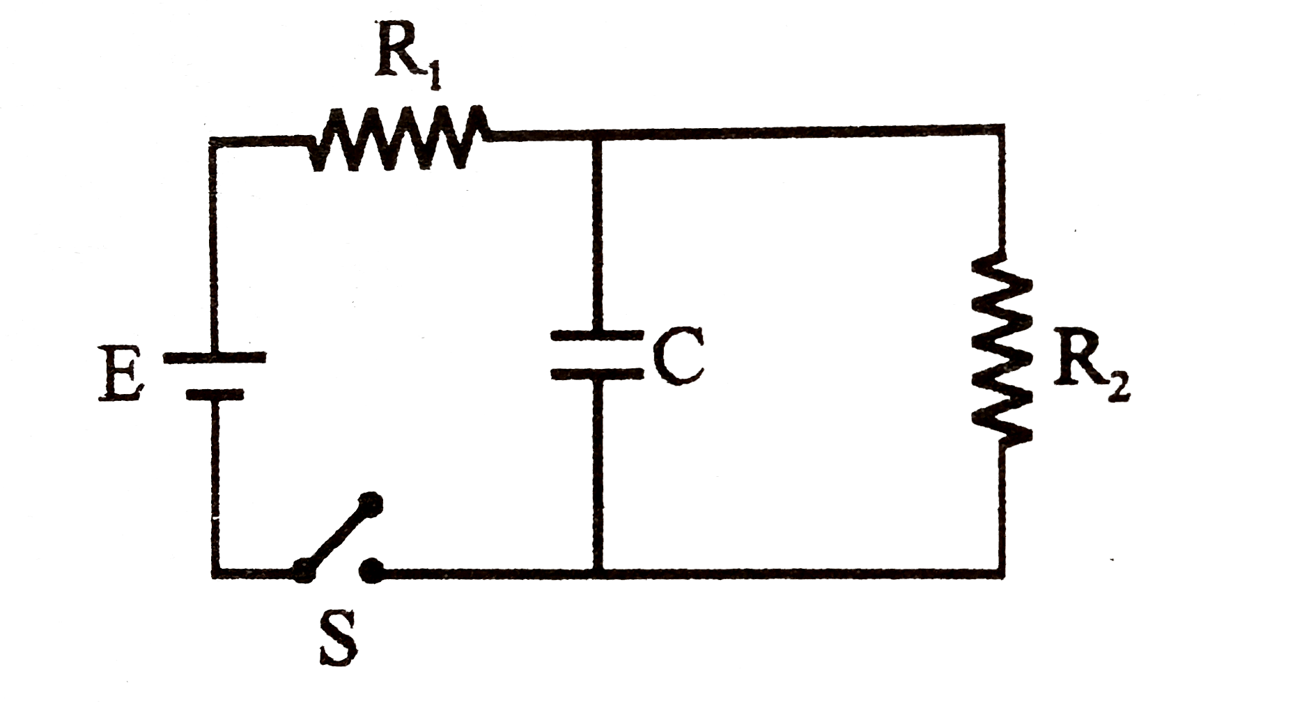
At the instant of closing the switch
View Solution
