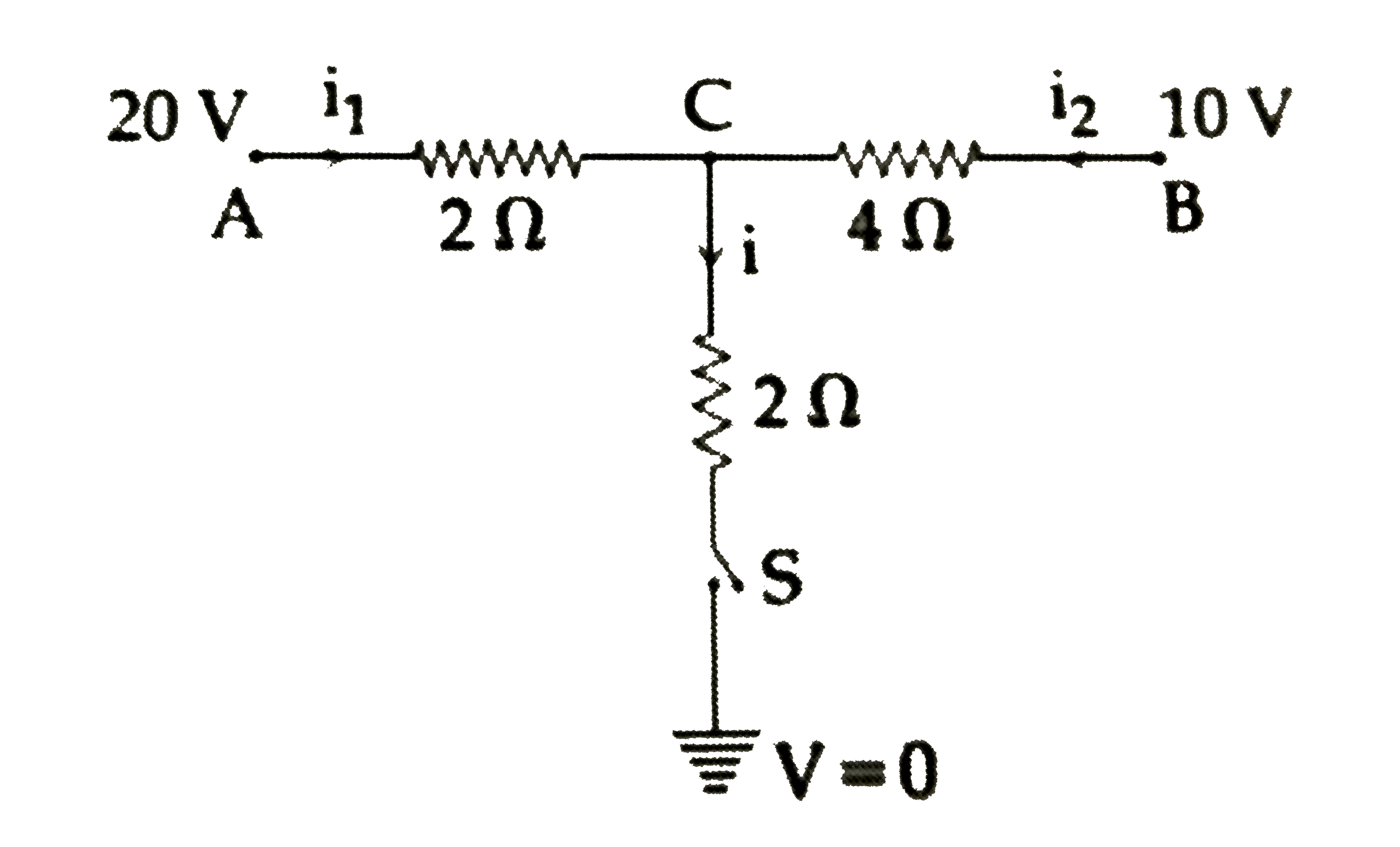
In the circuit shown all the ammeters are ideal.
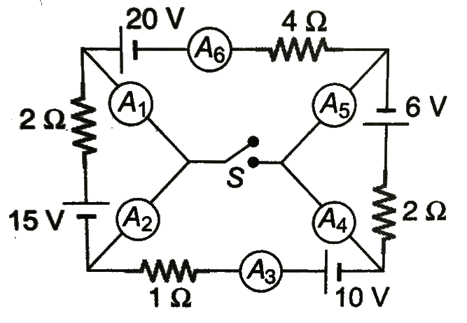
(a), If the switch S is open, find the reading of all ammeters and the potential difference across the switch.
(b) If the switch S is closed, find the current through all ammeters and the switch also.
The correct Answer is:A, B
NA
Topper's Solved these Questions
- CURRENT ELECTRICITYBook:DC PANDEY ENGLISHChapter:CURRENT ELECTRICITYExercise:Example
Explore 65 Videos
- CURRENT ELECTRICITYBook:DC PANDEY ENGLISHChapter:CURRENT ELECTRICITYExercise:Check point
Explore 70 Videos
- CURRENT ELECTRICITYBook:DC PANDEY ENGLISHChapter:CURRENT ELECTRICITYExercise:Level 2 Comprehension Example Type
Explore 2 Videos
- COMMUNICATION SYSTEMBook:DC PANDEY ENGLISHChapter:COMMUNICATION SYSTEMExercise:Subjective
Explore 11 Videos
- ELECTROMAGNETIC INDUCTIONBook:DC PANDEY ENGLISHChapter:ELECTROMAGNETIC INDUCTIONExercise:Medical entrances gallery
Explore 25 Videos
Similar Questions
When the switch is closed find the charge flown through switch?
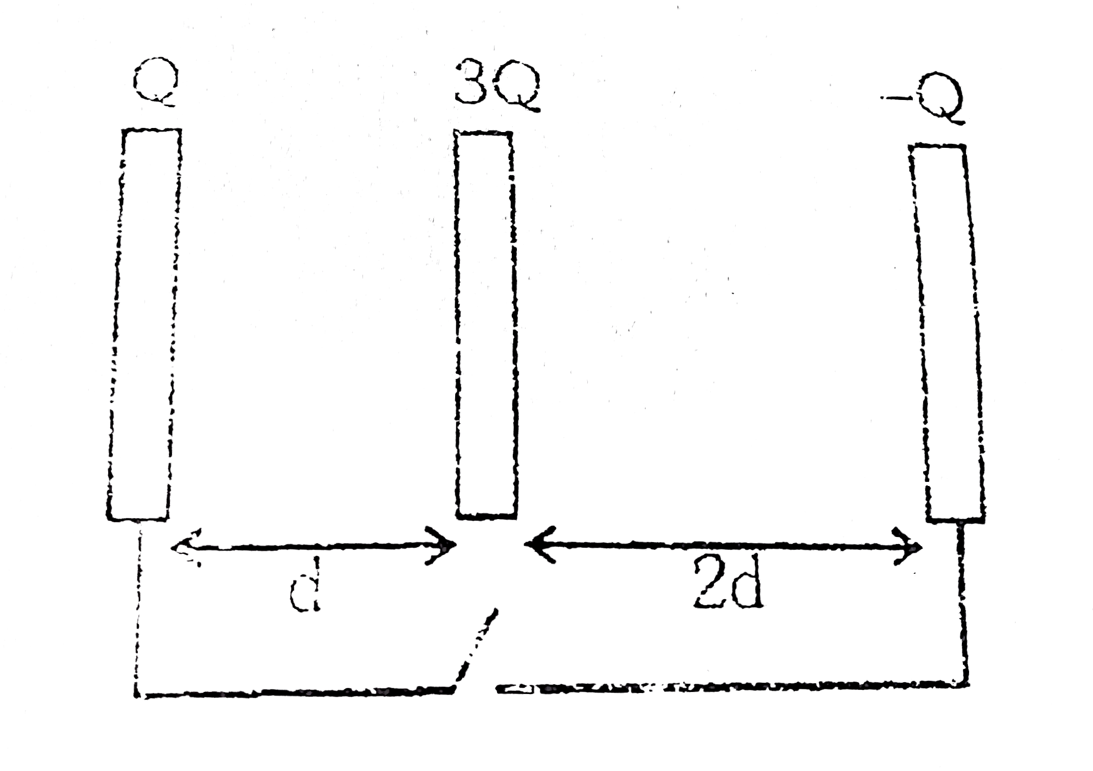
View SolutionFind the charge flown when the switch S is closed.
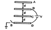
View SolutionIn the circuit shown in fig, switch S was closed for long time. At time t-0, the switch is opened again. The maximum potential difference across the plates of the capacitor after the switch is opened is

View SolutionIn the circuit in Fig. switch S1 was closed for a long time . At time t=0 the switch is opened.
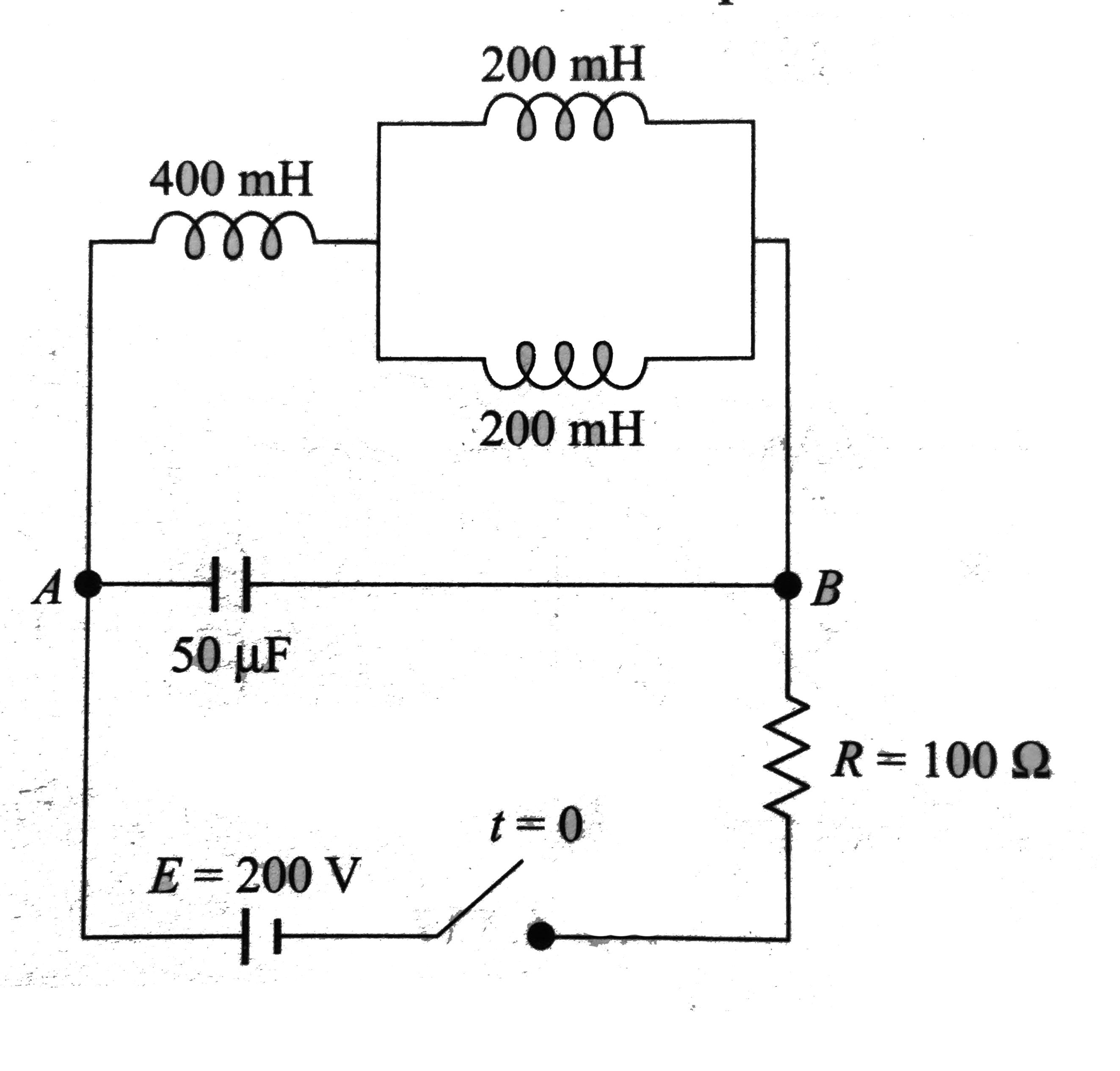
Find the maximum potentail difference across the plates of the capacitor after the switch is opened.
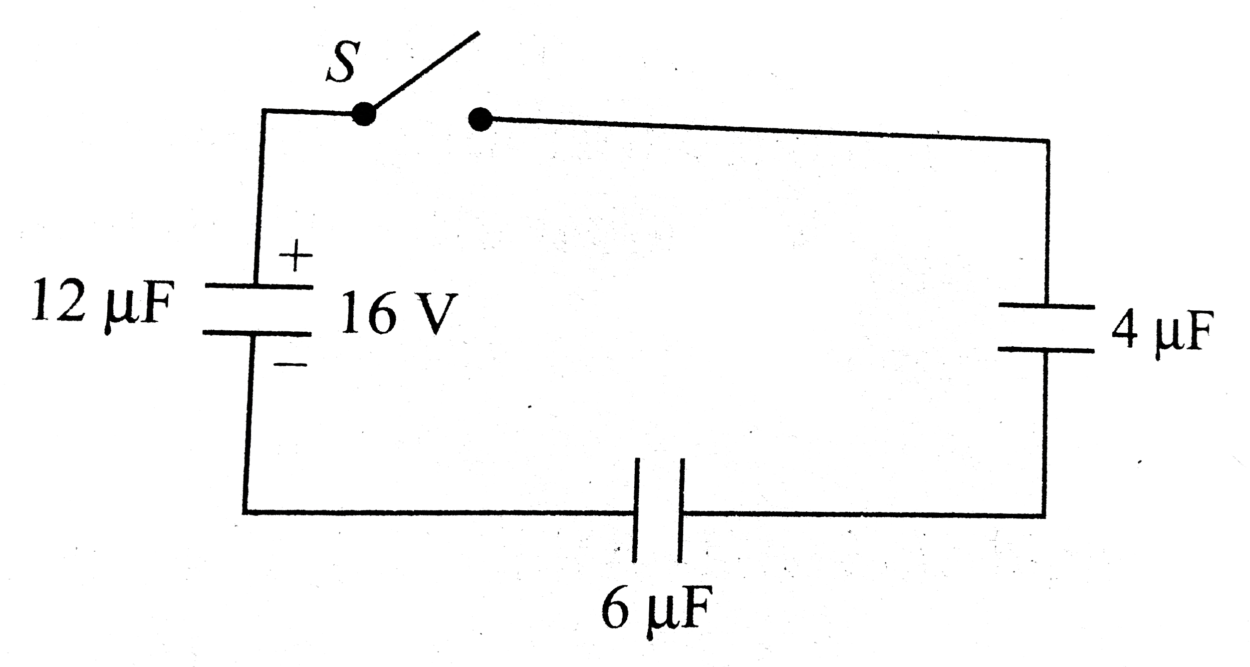
View SolutionIn the arrangement shown in, When the switch S is closed, find
 .
.
the final potential difference across the 12μF capacitor.
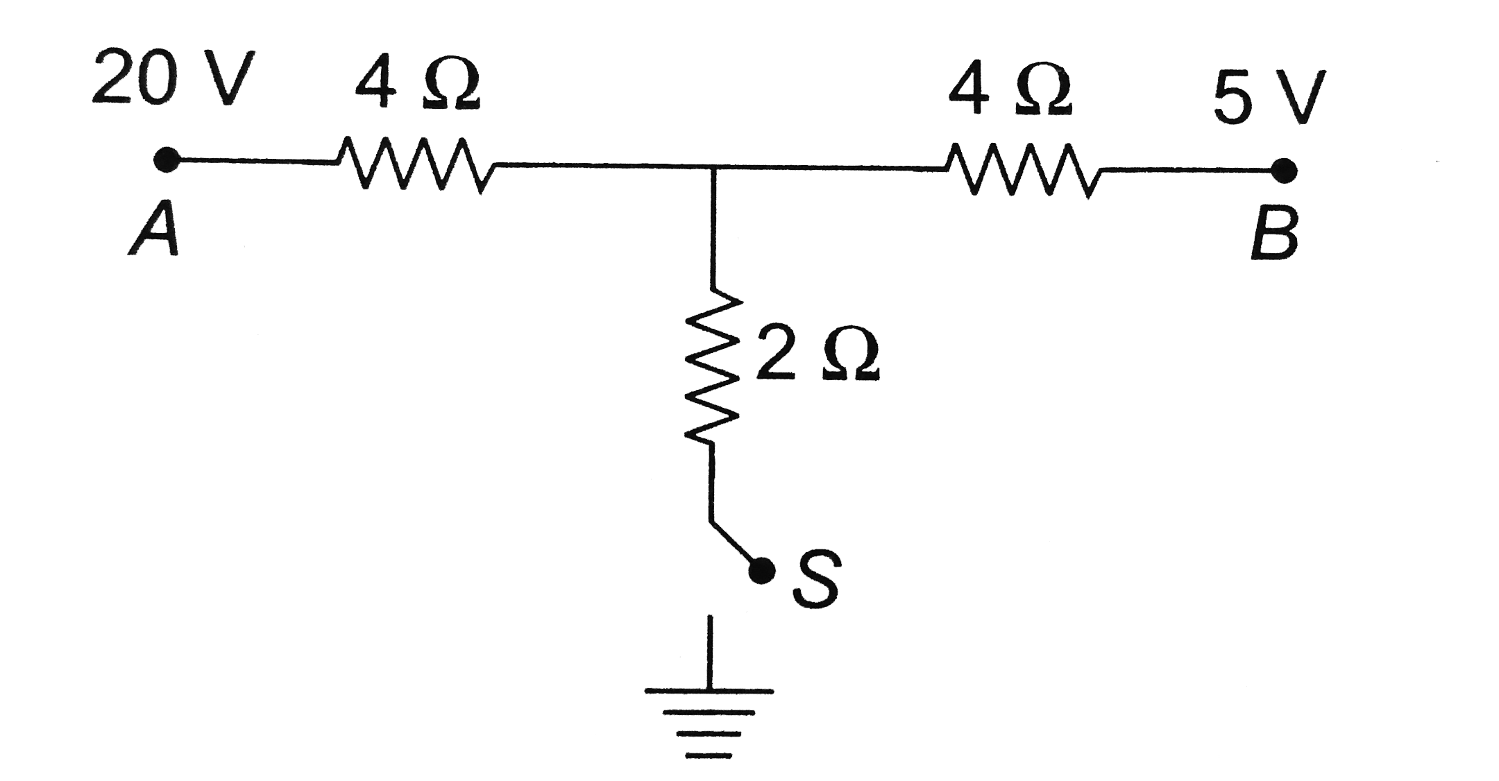
View Solutionshows three resistances are
connected with switch S initially the switch is open. When
the switch S is closed find the current passed through it.
View SolutionAs the switch S is closed in the circuit shown in figure, current passed through it is.
View SolutionIn the arrangement shown in , the switch S is find
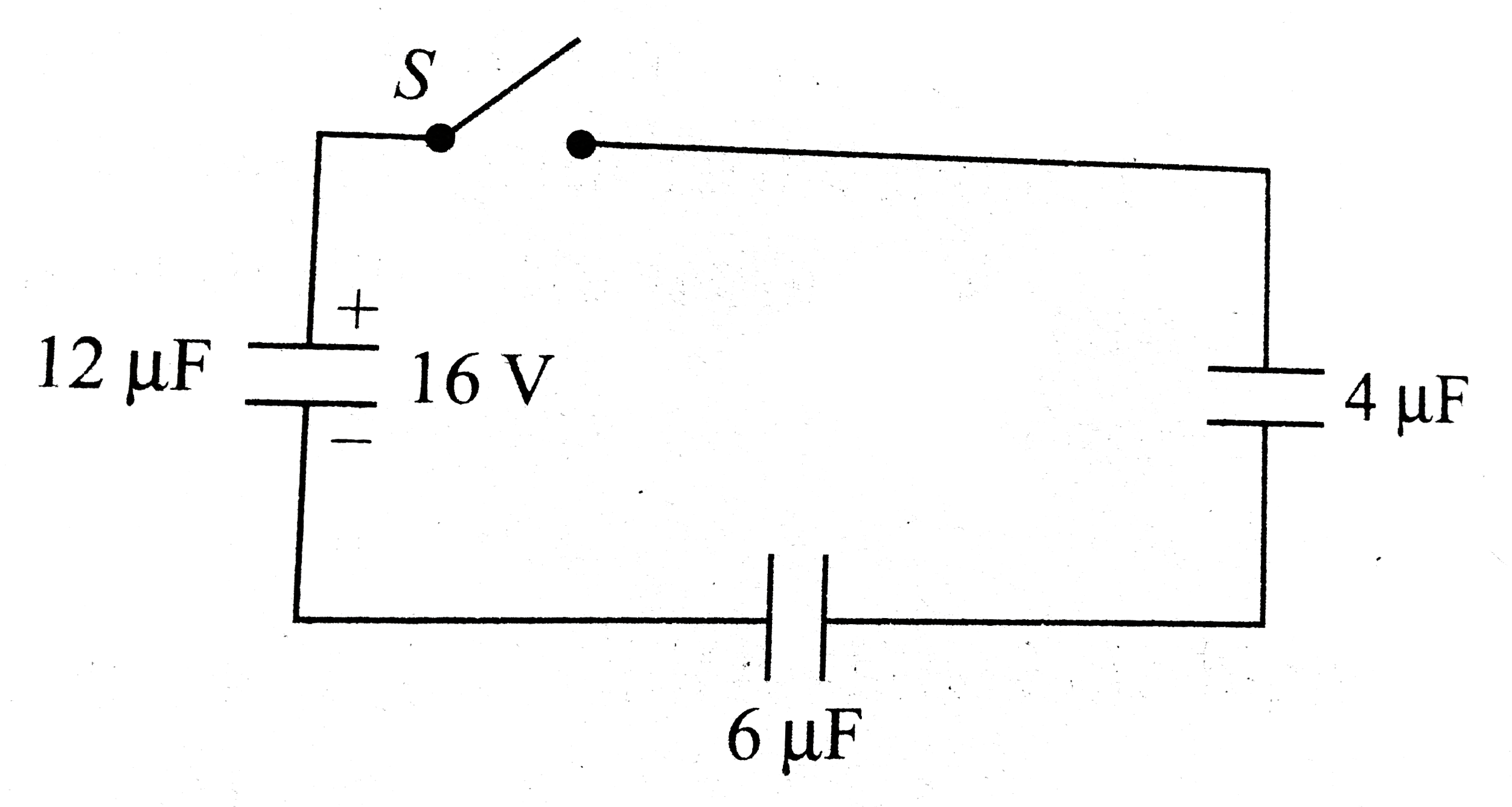 the final potential difference across the 4μF capacitor
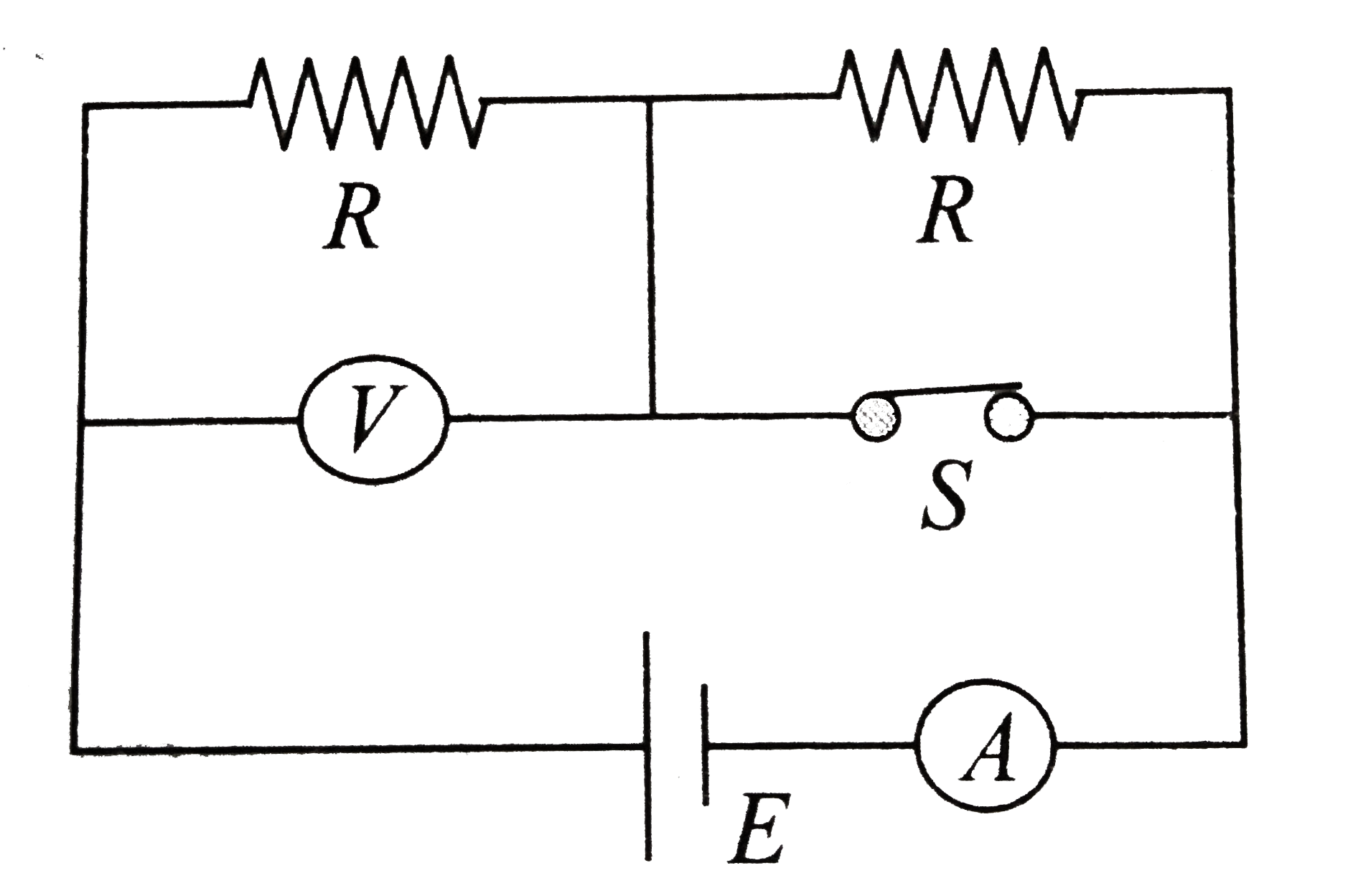
View SolutionIn the circuit shown, battery, ammeter , and voltmeter are ideal and the switch S is initially closed as shown. When switch S is opened
View SolutionWhen the switch S, in the circuit shown, is closed, then the value of current I will be :
View Solution
