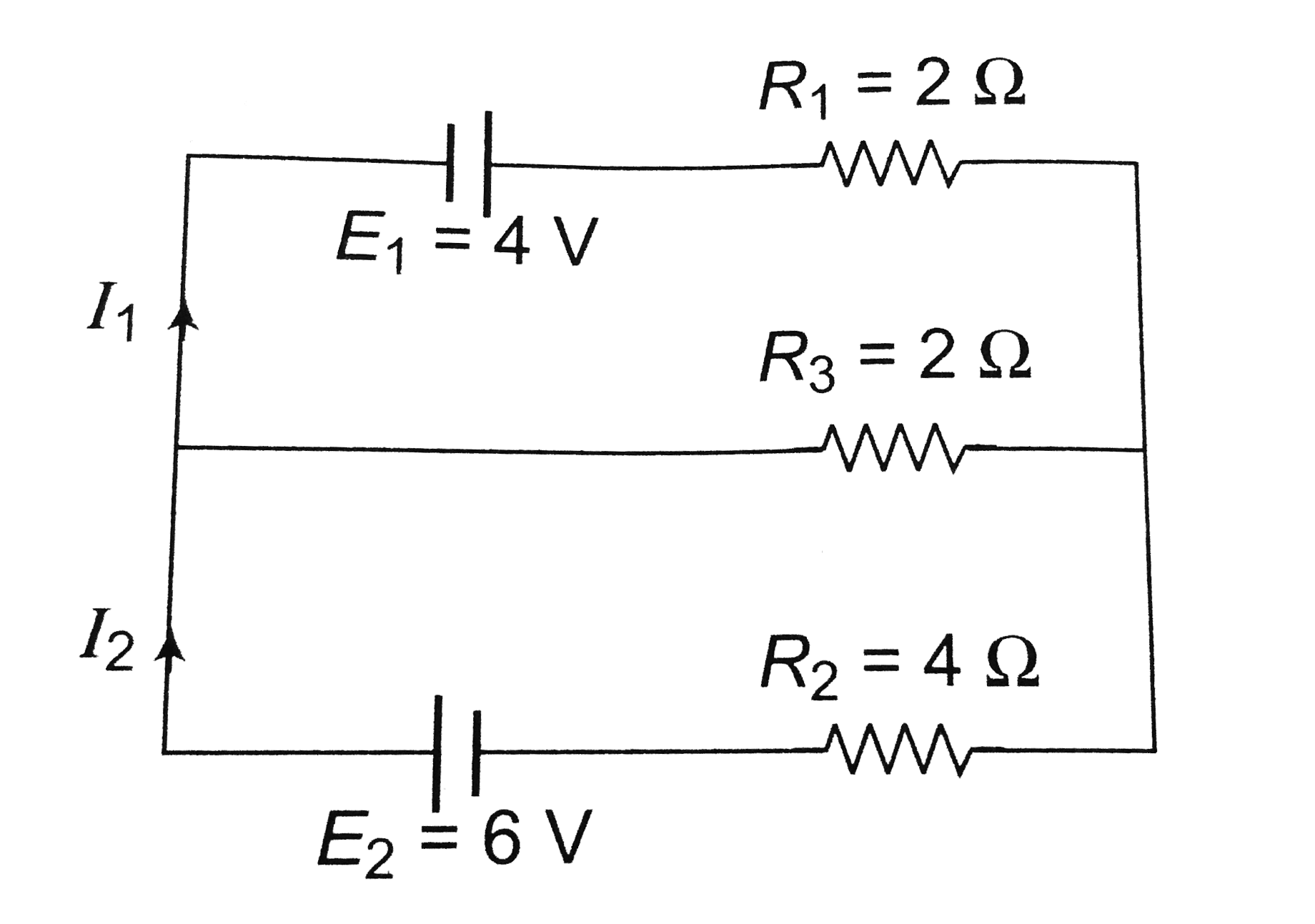
In the circuit shown below E1=4.0V,R1=2Ω,E2=6.0V,R2=4Ω and R3=2Ω. The current I1 is
1.6A
1.8A
1.25A
1.0A
The correct Answer is:B
Step by step video & image solution for In the circuit shown below E_(1) = 4.0 V, R_(1) = 2 Omega, E_(2) = 6.0 V, R_(2) = 4 Omega and R_(3) = 2 Omega. The current I_(1) is by Physics experts to help you in doubts & scoring excellent marks in Class 12 exams.
Topper's Solved these Questions
- BOOK - CENGAGE PHYSICS ENGLISHCHAPTER - ELECTRIC CURRENT & CIRCUITSEXERCISE - Kirchhoff s Law and Grouping Cells15videos
ELECTRIC CURRENT & CIRCUITS
- BOOK - CENGAGE PHYSICS ENGLISHCHAPTER - COULOMB LAW AND ELECTRIC FIELDEXERCISE - Single Answer Correct Type22videos
COULOMB LAW AND ELECTRIC FIELD
- BOOK - CENGAGE PHYSICS ENGLISHCHAPTER - ELECTRIC CURRENT AND CIRCUITEXERCISE - Interger8videos
ELECTRIC CURRENT AND CIRCUIT
Similar Questions
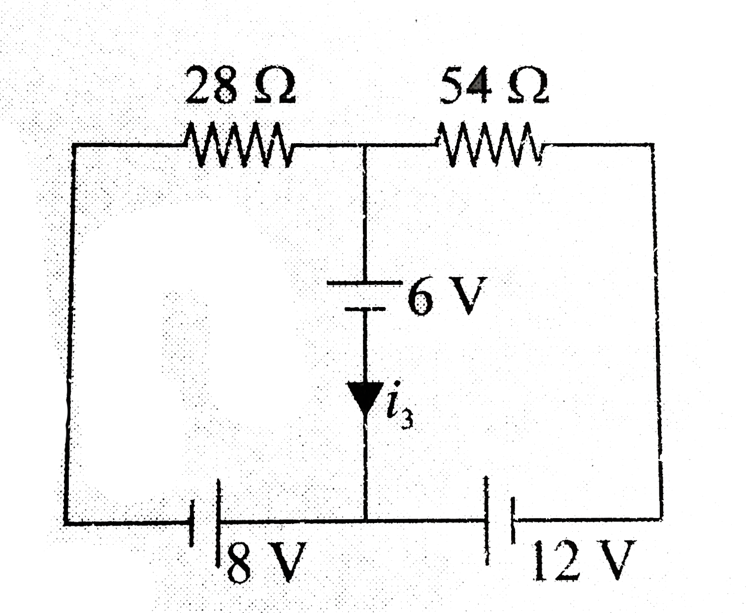
In the following circuit ,E1=4V,R1=2Ω,
E2=6V,R2=2Ω,andR3=4Ω. Find the currents i1andi2
 View Solution
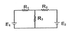
In the circuit shown, E1=7V,E2=7V,R1=R2=1Ω and R3=3Ω respectively. The current through the resistance R3
 View Solution
In the circuit shown, E1=7V,E2=7V,R1=R2=1Ω and R3=3Ω respectively. The current through the resistance R3
 View Solution
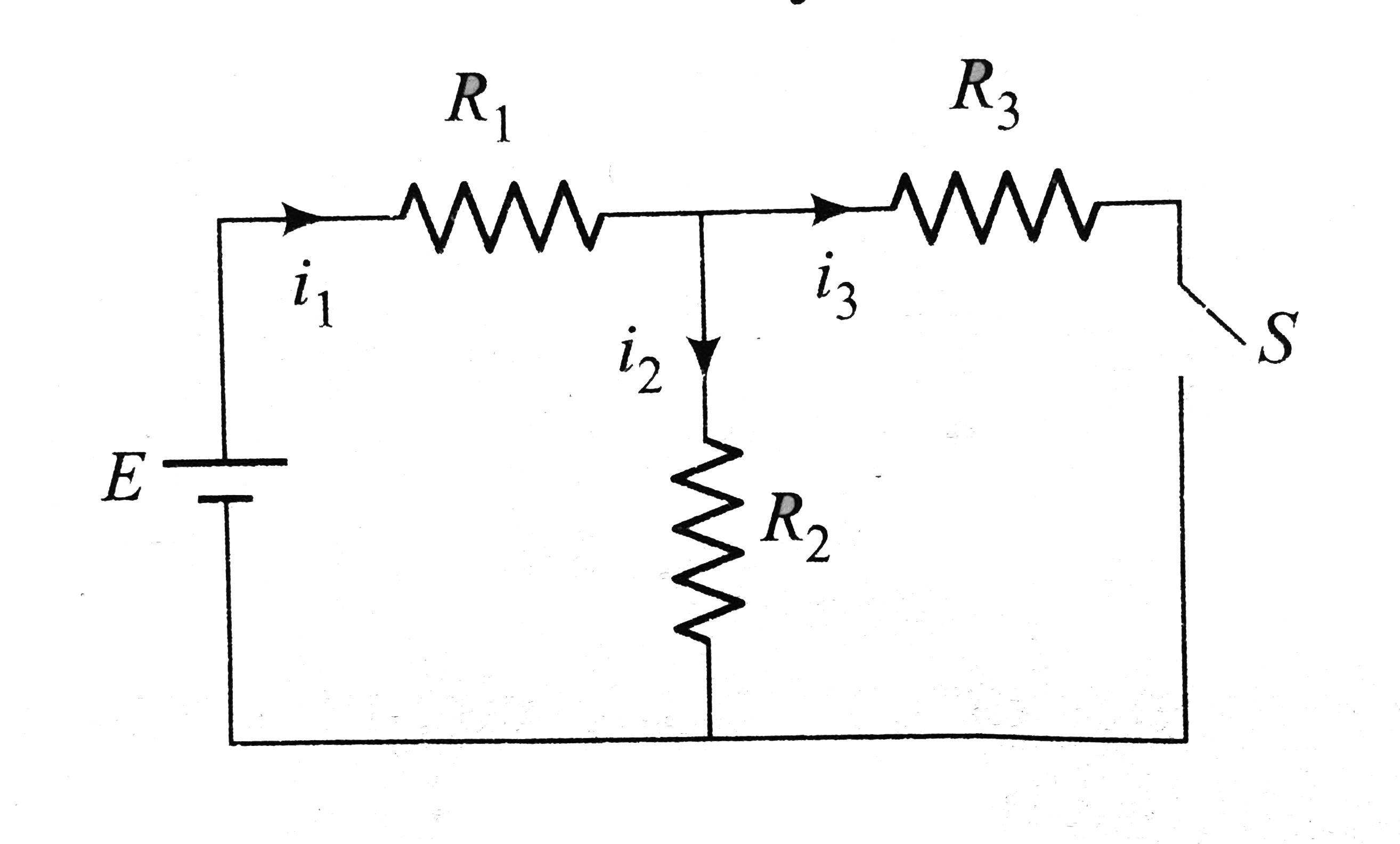
In the circuit shows in Fig E=15V, R1=1Ω, R2=1Ω, R3=2Ω, and L=1.5H. The currents flowing through R1,R2,and R3 are i1,i2, and i3, respectively.
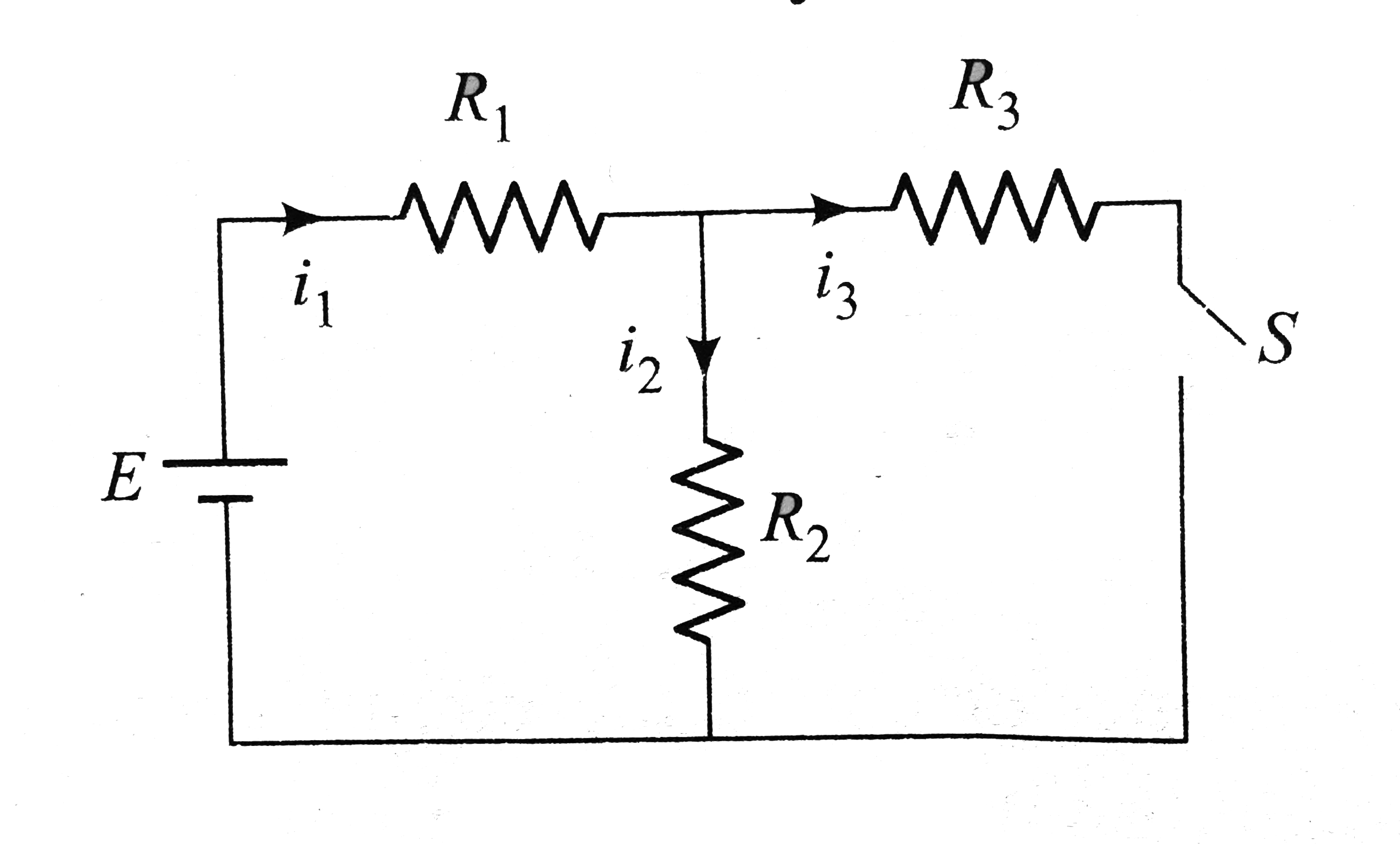
Immediately after connecting switch S,View SolutionIn the circuit shows in Fig E=15V, R1=1Ω, R2=1Ω, R3=2Ω, and L=1.5H. The currents flowing through R1,R2,and R3 are i1,i2, and i3, respectively.
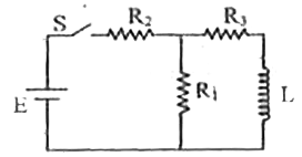
Immediately after tuning switch S on,View SolutionFor the circuit shown E=50 V R1=10Ω,R2=20Ω,R3=30Ω L = 2.0 mH . The current through R1 and R2 are ________ . immediate after the switch is closed.
 View Solution
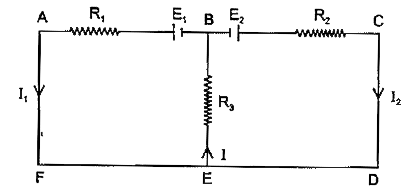
In the circuit shown below, E1=17V,E2=21V,R1=2Ω,R2=3ΩandR3=5Ω. Using Kirchhoff.s laws, find the currents flowing through the resistors R1,R2 and R3. (Internal resistance of each of the batteries is negligible.)
 View Solution
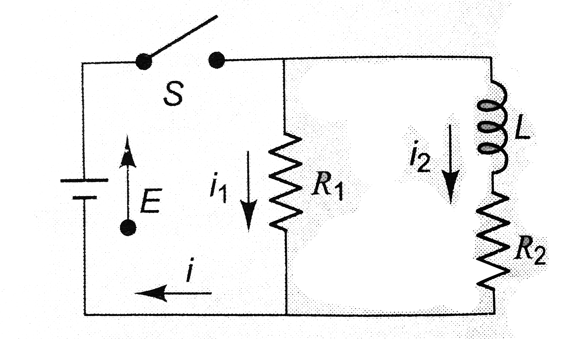
In the circuit shows in Fig. , E=10V, R1=5Ω, R2=10Ω, and L=5H. For the two separate conditions, (i) switch S is just closed and (ii) switch S is closed for a long time, calculate
a. current i1 through R1,
b. current i2 through R2,
c. current i through the switchs,
d. the potential difference across R2,
e. the potential difference across L,
f. di2/dt.
 View Solution
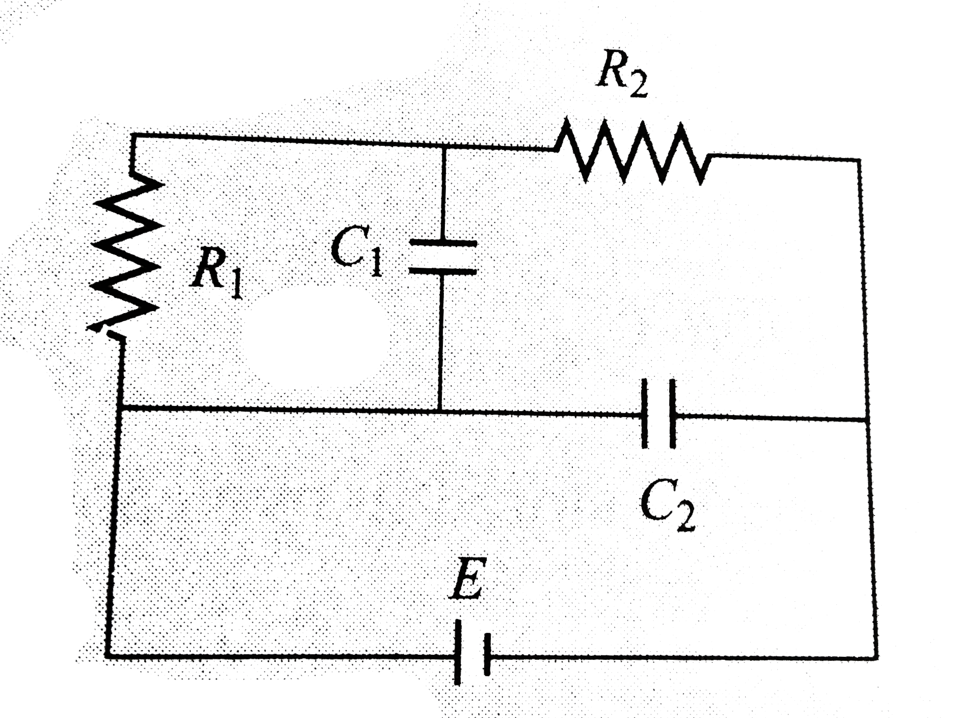
In the circuit shown in fig. R1=10Ω,R2=5Ω,C1=1μF,C2=2μF, and E =6V. Calculate the charge on each capactor in the stedy state.
 View Solution
In the circuit shown in figure, R(1)=1Ω,R2=2Ω,C1=1μF,C2=2μF and E=6V. Calculate charge on each capacitor in steady state
 View Solution

