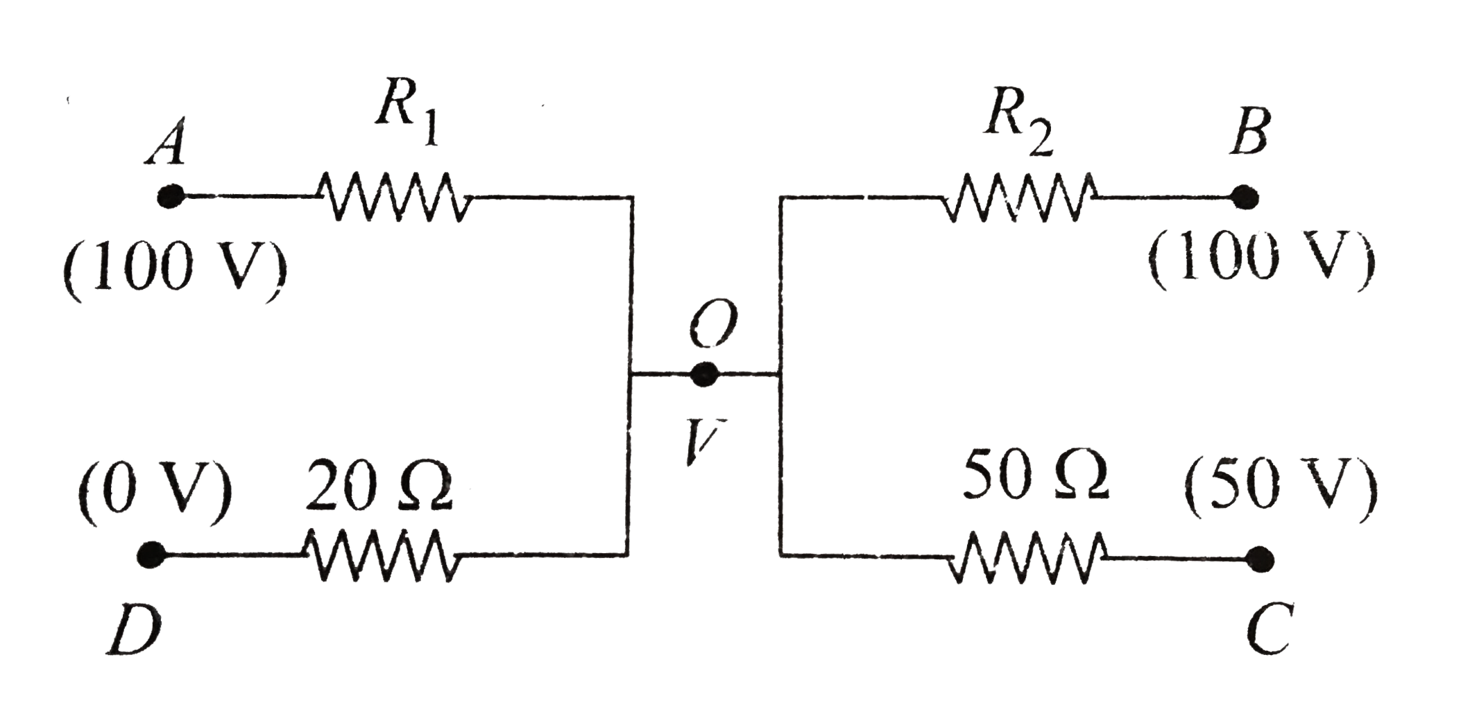
The circuit is shown in the following figure. The potential at points A, B, C, D and O are given. The currents in the resistance R1,R2 and R3 are in the ratio of 4:2:1. What is the ratio of resistance R1,R2,R3 and R4 ?
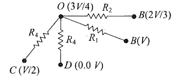
3:2:12:16
2:3:36:12
4:3:12:32
3:4:14:32
The correct Answer is:A
Step by step video & image solution for The circuit is shown in the following figure. The potential at points A, B, C, D and O are given. The currents in the resistance R_(1), R_(2) and R_(3) are in the ratio of 4:2:1. What is the ratio of resistance R_(1),R_(2),R_(3) and R_(4) ? by Physics experts to help you in doubts & scoring excellent marks in Class 12 exams.
Updated on:21/07/2023Topper's Solved these Questions
- ELECTRIC CURRENT & CIRCUITSBook:CENGAGE PHYSICS ENGLISHChapter:ELECTRIC CURRENT & CIRCUITSExercise:Kirchhoff s Law and Grouping Cells
Explore 15 Videos
- COULOMB LAW AND ELECTRIC FIELDBook:CENGAGE PHYSICS ENGLISHChapter:COULOMB LAW AND ELECTRIC FIELDExercise:Single Answer Correct Type
Explore 22 Videos
- ELECTRIC CURRENT AND CIRCUITBook:CENGAGE PHYSICS ENGLISHChapter:ELECTRIC CURRENT AND CIRCUITExercise:Interger
Explore 8 Videos
Similar Questions
Knowledge Check
In the shown in the given figure, the resistances R1andR2 are respectively
 A14Ωand40ΩB40Ωand44ΩC40Ωand30ΩD14Ωand30Ω
If in a Δ the ex-reddii r1r2r3 are in the ratio 1:2:3 then their sides are in the ratio :-
View SolutionThe given circuit has two ideal diodes connected as shown in the figure below. The current flowing through the resistance R1 will be
View SolutionIn the given circuit the cells have zero internal resistance. The currents (in Amperes) passing through resistance R1andR2 respectively, are :
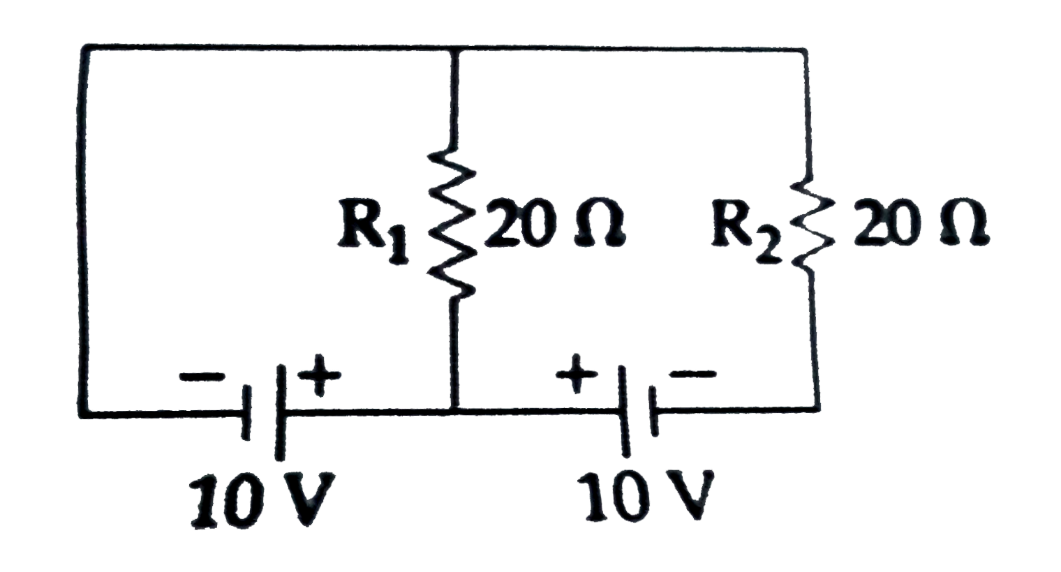
View SolutionIn the given circuit, if I1andI2 be the current in resistances R1andR2, respectively, then
 .
.
View SolutionIn the circuit as shown, it is given that R1/R2=1/2 and potential at O is V.
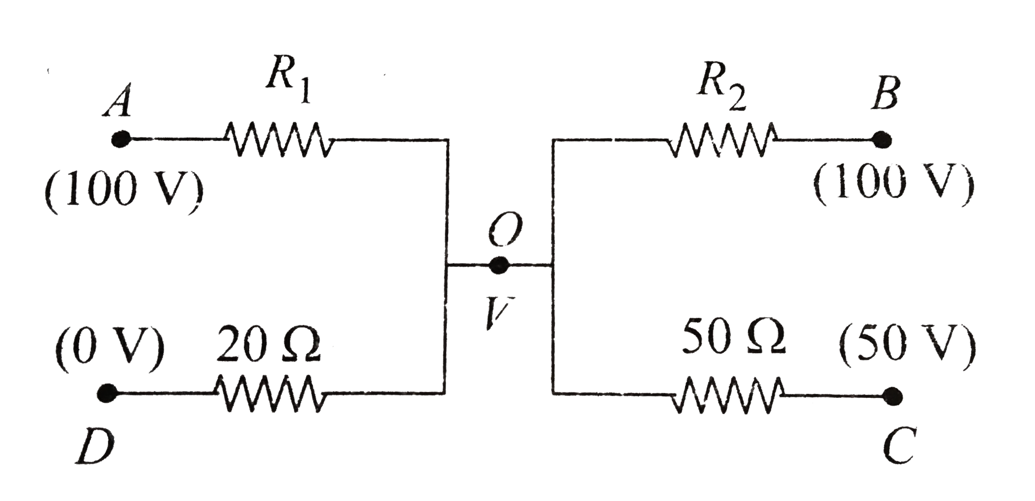
View SolutionIn the circuit as shown, it is given that R1/R2=1/2 and potential at O is V.
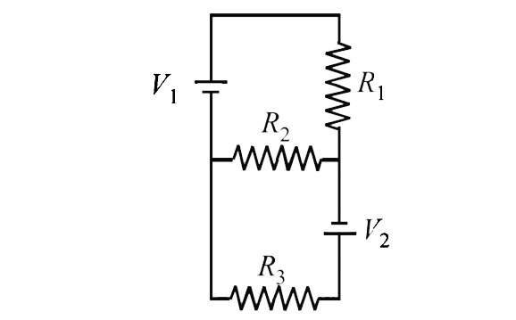
View SolutionTwo ideal batteries of emf V1andV2 and three resistances R1,R2andR3 are connected as shown in the figure. The current in resistance R2 would be zero if
View Solution

