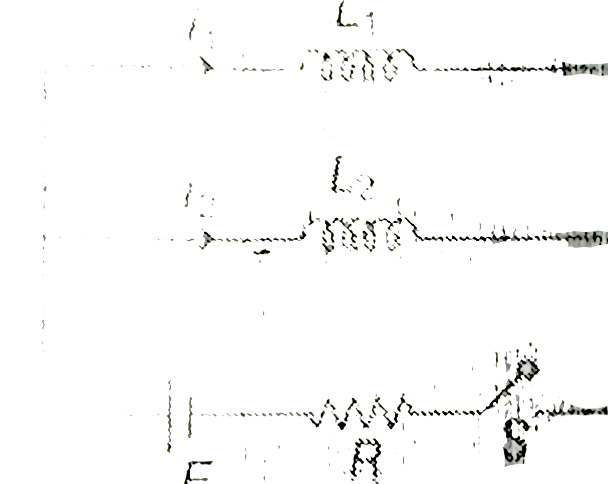
In the circuit shown in Fig. emfE , a resistance R, and coil inductances L1 and L2 are known. The internal resistance of the source and the coil resistances are neglible. Find the steady-state currents in the coils after the swich Sw was shorted.

Step by step video & image solution for In the circuit shown in Fig. emf E , a resistance R, and coil inductances L_(1) and L_(2) are known. The internal resistance of the source and the coil resistances are neglible. Find the steady-state currents in the coils after the swich Sw was shorted. by Physics experts to help you in doubts & scoring excellent marks in Class 12 exams.
Topper's Solved these Questions
- BOOK - PHYSICS GALAXY - ASHISH ARORACHAPTER - ELECTROMAGNETIC INDUCTION AND ALTERNATING CURRENTEXERCISE - Illustration25videos
ELECTROMAGNETIC INDUCTION AND ALTERNATING CURRENT
- BOOK - PHYSICS GALAXY - ASHISH ARORACHAPTER - ELECTROMAGNETIC INDUCTION AND ALTERNATING CURRENTEXERCISE - Practice Exercise 5.112videos
ELECTROMAGNETIC INDUCTION AND ALTERNATING CURRENT
- BOOK - PHYSICS GALAXY - ASHISH ARORACHAPTER - CURRENT ELECTRICITYEXERCISE - All Questions389videos
CURRENT ELECTRICITY
- BOOK - PHYSICS GALAXY - ASHISH ARORACHAPTER - ELECTROSTATICSEXERCISE - Unsolved Numberical Problems73videos
ELECTROSTATICS
Similar Questions
Two coils of self inductance L1 and L2 are connected in parallel and then connected to a call of emf ε and internal resistance - R. Find the steady state current in the coils.
View SolutionTwo coils of self inductance L1 and L2 are connected by in parllel and the then to cell of emf ε and of resistance R throught a Key . Find the instantaneous current throught L after the key is closed .
View Solution
Knowledge Check
- Question 1 - Select One
In the circuit shown in the figure The steady state currents i1andi2 in the coils after the switch S is closed are
 Ai1=EL2R(L1+L2)Bi1=EL1R(L1+L2)Ci2=EL2R(L1+L2)Di2=E√L1L2RL2
 - Question 2 - Select One or More
In the circuit, a battery of emf E, a resistance R and inductance coil L1andL2 and switch S are connected as shown. In Fig. Initially the switch is open
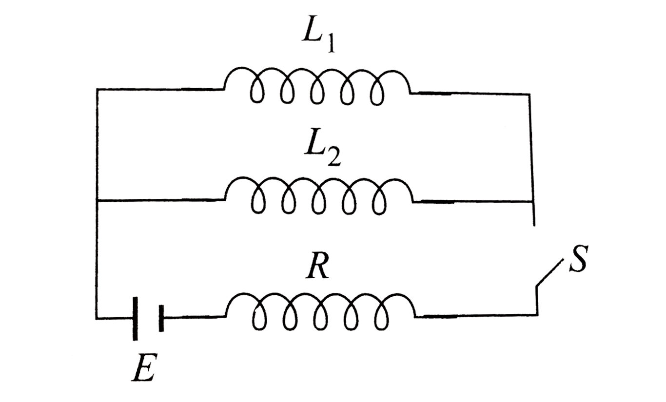 AThe time constant of the circuit is 1RL1L2L1+L2BSteady state current in the inductor L1is(EL_(2))/(R(L_(1)+L_(2)))CSteady state current in the inductor L2 is EL1R(L1+L2)DIn steady the total energy stored in the inductor coils is 12L1L2L1+L2E2R2
 - Question 3 - Select One
A coil resistance R and inductance L is connected to a battery of emf E volt. The final current in the coil is
AERBELC√(ER2+L2)D√(ELR2+L2)
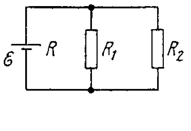
In the circuit shown in Fig. the emf of the sources is equal to ξ=5.0V and the resistances are equal to R1=4.0Ω and R2=6.0Ω. The internal resistance of the source equals R=1.10Ω. Find the currents flowing through the resistances R1 and R2.
 View Solution
A coil inductance L and resistance R is connected to a constant voltage source. How soon will the coil current attains η(η<1) fraction of the steady state value?
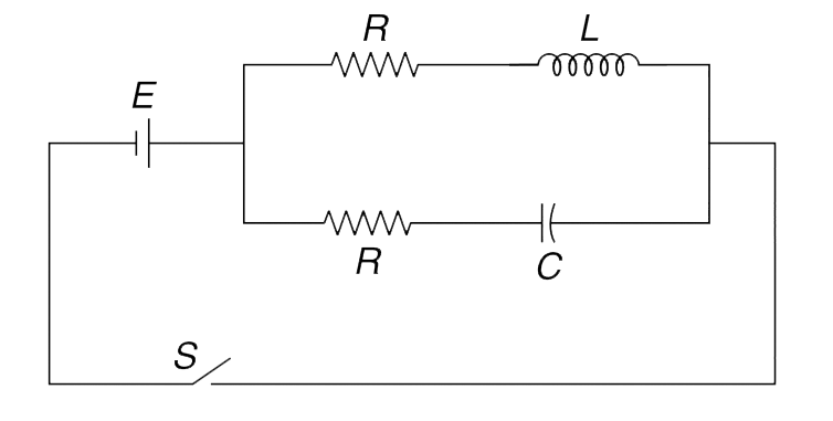
View SolutionIn the circuit shown, find the value of resistance R in terms of inductance L and capacitance C such that the current through the cell remains constant forever after the switch is closed.
 View Solution
In fig the steady state current in 2ω resistance is
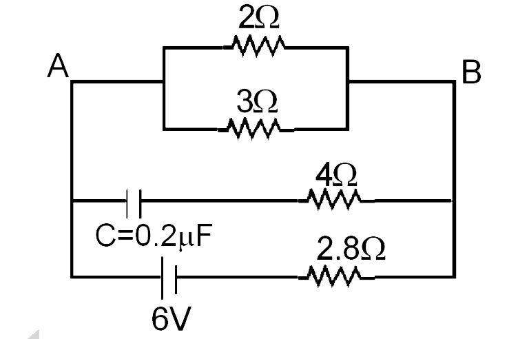 View Solution
If L and R be the inductance and resistance of the choke coil, then indentify the correct statement
View Solution

