In the circuit shown in Fig.a voltage V is connected across lamp L. What changes would occur at lamp and the voltage V, if the resistance R is reduced in value?
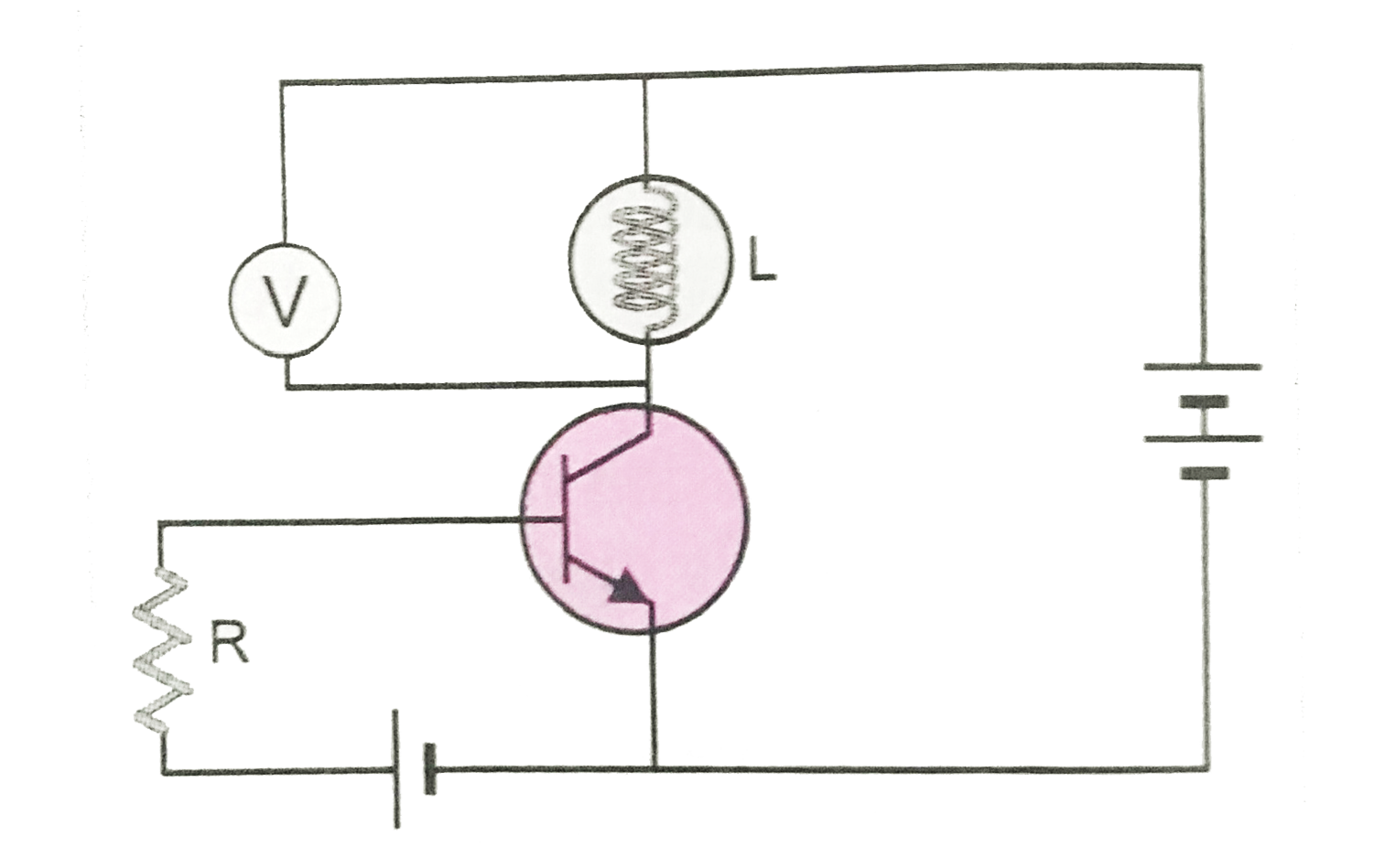
Here emitter base junction of npn transistor is forward biased with a battery and resistance R. If value of R is reduced, then the current in the input circuit increases and hence emitter current Ie increases.
Therefore the collector current Ic=Ie−Ib will also increase. Due to it the bulb will glow more brillantly.
voltage V measures the potential difference across lamp L. Due to increase in collector current, the potential difference across L increases, hence the reading of voltage will increase.
Topper's Solved these Questions
- ELECTRONIC DEVICESBOOK - PRADEEPCHAPTER - ELECTRONIC DEVICESEXERCISE - SAMPLE PROBLEM
2 Videos
- ELECTRONIC DEVICESBOOK - PRADEEPCHAPTER - ELECTRONIC DEVICESEXERCISE - CONCEPTUAL PROBLEMS
1 Videos
- ELECTROMAGNETIC WAVESBOOK - PRADEEPCHAPTER - ELECTROMAGNETIC WAVESEXERCISE - II Focus multiple choice question
5 Videos
- ELECTROSTATICSBOOK - PRADEEPCHAPTER - ELECTROSTATICSEXERCISE - ASSERTION-REASON TYPE QUESTIONS
2 Videos
Similar Questions
In a common emitter transistor circuit, a bulb B and a volmeter V are connected as shown in Fig.What change would take place in bulb B and volmeter V when the value of resistance R is increased?
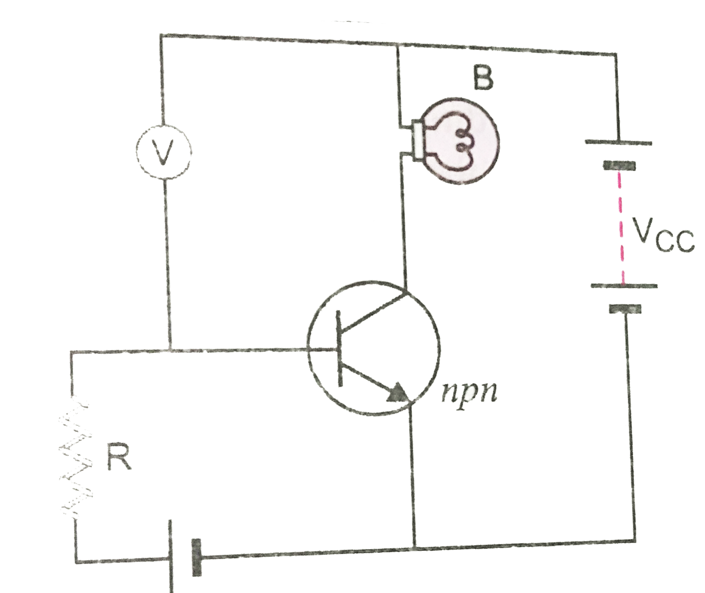
View SolutionIn the given circuit diagram, a voltmeter 'V' is connected across a lamp 'L'. How would (i) the brightness of the lamp and (ii) voltmeter reading 'V' be affected, if the value of resistance 'R' is decreased ? Justify your answer.
View Solution
Knowledge Check
In the following circuit, a voltmeter V is connected across a lamp L. What change would occure in voltmeter reading if the resistance R is reduced in value?
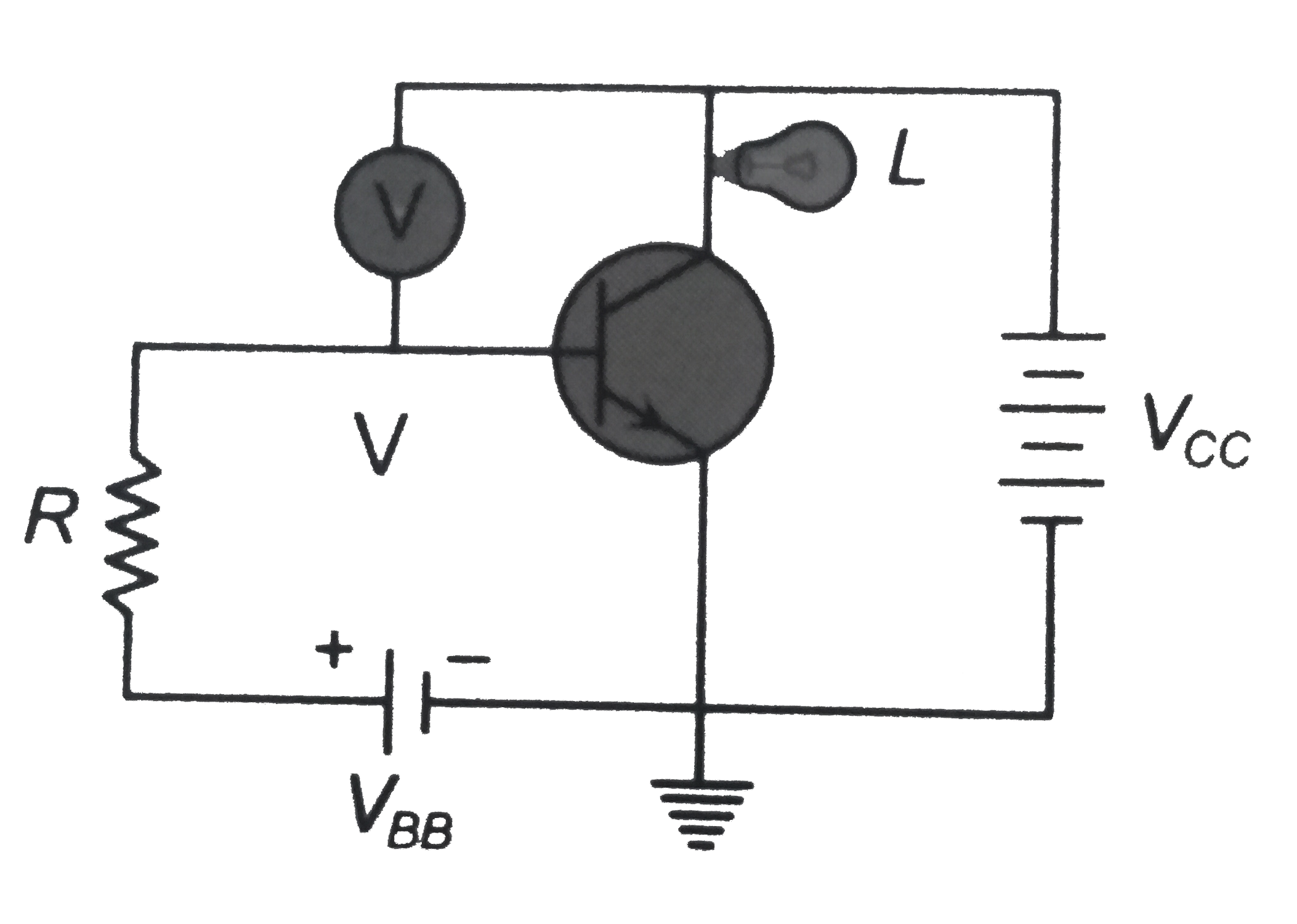 AIncreasesBDecreasesCRemains sameDNone of these
In the circuit shown in Fig. If both the lamps L1 and L2 are identical.
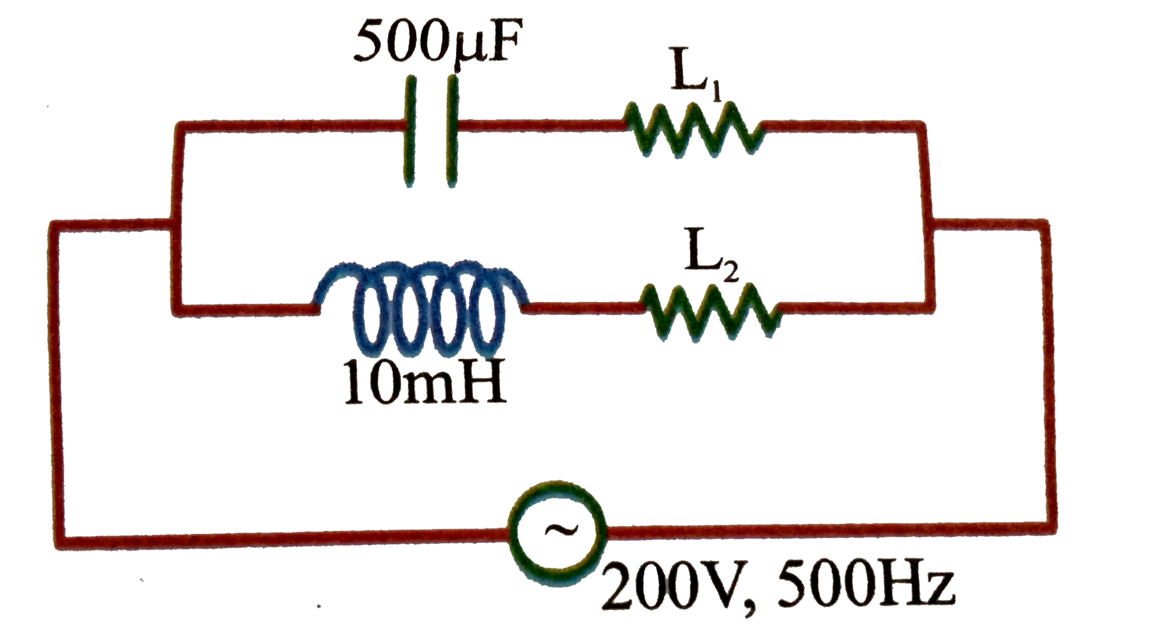 Atheir brightness will be sameBL1 will be brighter than L2CAs the frequency of supply voltage in increased, brightness of L1 will increase and that of L1 will decreaseDOnly L2 will glow because the capacitor has infinite resistance
In a series C−R circuit shown in figureure, the applied voltage is 10V and the voltage across capacitor is found to8V. The voltage across R, and the phase difference between current and the applied voltage will respectively be
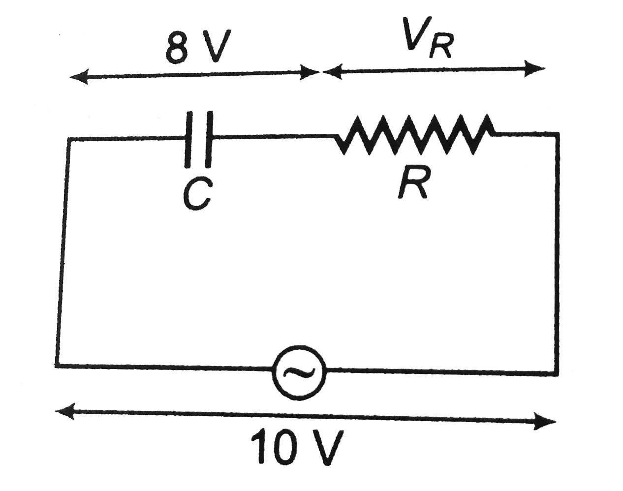 .A6V,tan−1(43)B3V,tan−1(34)C6V,tan−1(34)Dnone of these
An amplifier is represented by the circuit shown in Fig. Here ri is the input resistance of the amplifier and the voltage Vi is appearing across it. This voltage is amplified by a factor AV and appears across the load as voltage V0
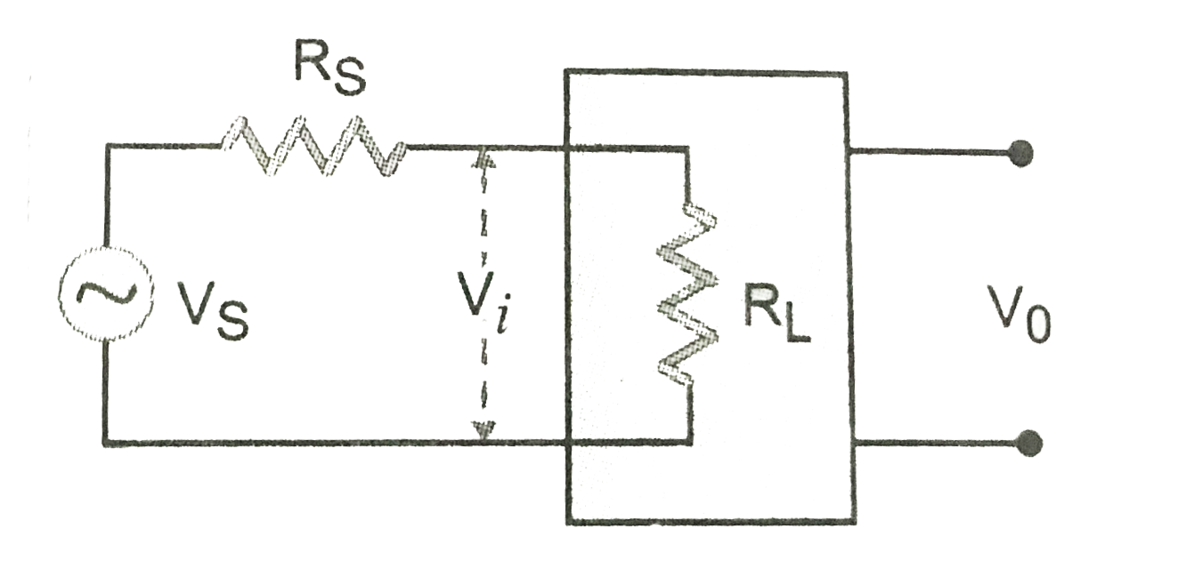
An external voltage Vs is applied at the input terminals of the amplifier via series resistance RS. What will be the apparent gain AV(=V0/Vs) of the ampilifier in terms of AV,RS and ri.
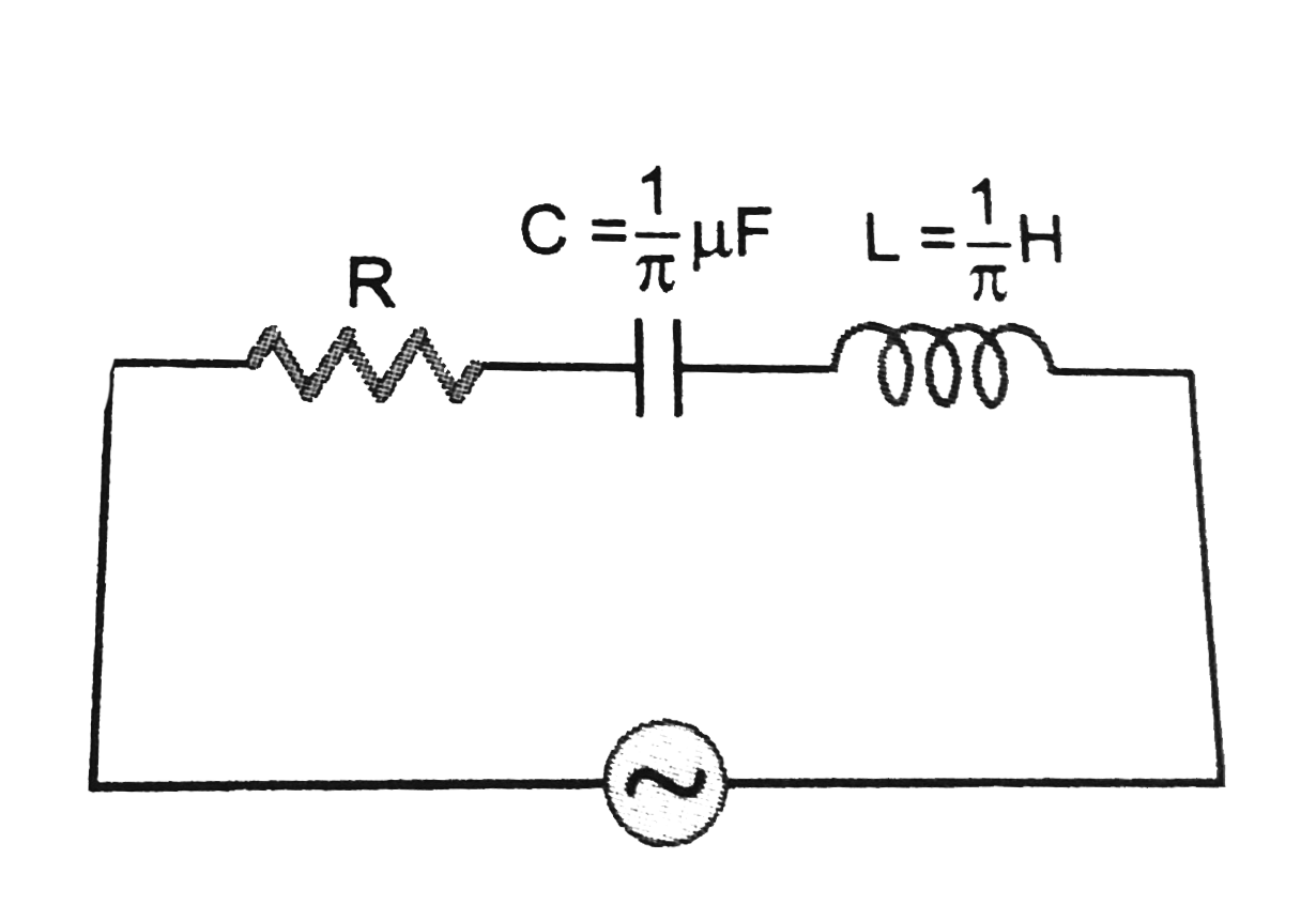
View SolutionIn the a.c. circuit shown in fig, the main supply hs constant voltage but variable frequency. For what frequency will the voltage across the resistance R be maximum ?
View SolutionA sinusoidal voltage of rms value 200 volt is connected to a diode and a resistor R in the circuit as shown in Fig., so that half wave rectification occurs. If the diode is ideal, what is the rms voltage across R? If resistor R is replaced by capactior of capacitance C, find the potential difference across C.

View SolutionThe series L–C–R circuit shown in fig. is in resonance state. What is the voltage across the inductor?
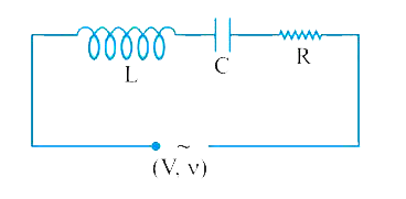
View SolutionIn a series CR circuit shown in figure,the applied voltage is 10V and the voltage across capacitor is found to be 8V
View Solution
