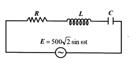
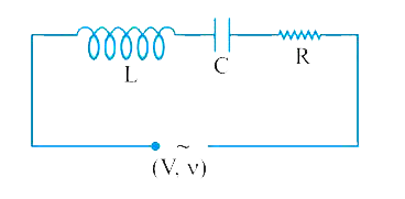
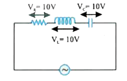
The series L–C–R circuit shown in fig. is in resonance state. What is the voltage across the inductor?
Video Solution
Text Solution
Current at resonance I=VR.
∴ Voltage across inductor VL=I.XL=IωL=VR(2πv)L.
|
Topper's Solved these Questions
- UNIT–III & UNIT–IV MAGNETIC EFFECTS OF CURRENT AND MAGNETISM & E.M.I. AND ALTERNATING CURRENTBook:CBSE COMPLEMENTARY MATERIALChapter:UNIT–III & UNIT–IV MAGNETIC EFFECTS OF CURRENT AND MAGNETISM & E.M.I. AND ALTERNATING CURRENTExercise:SHORT ANSWERS QUESTIONS (3 Marks)
Explore 27 Videos
- UNIT–III & UNIT–IV MAGNETIC EFFECTS OF CURRENT AND MAGNETISM & E.M.I. AND ALTERNATING CURRENTBook:CBSE COMPLEMENTARY MATERIALChapter:UNIT–III & UNIT–IV MAGNETIC EFFECTS OF CURRENT AND MAGNETISM & E.M.I. AND ALTERNATING CURRENTExercise:LONG ANSWER QUESTIONS (5 Marks)
Explore 5 Videos
- UNIT–III & UNIT–IV MAGNETIC EFFECTS OF CURRENT AND MAGNETISM & E.M.I. AND ALTERNATING CURRENTBook:CBSE COMPLEMENTARY MATERIALChapter:UNIT–III & UNIT–IV MAGNETIC EFFECTS OF CURRENT AND MAGNETISM & E.M.I. AND ALTERNATING CURRENTExercise:(NUMERICALS)
Explore 57 Videos
- SAMPLE QUESTION PAPER 2019Book:CBSE COMPLEMENTARY MATERIALChapter:SAMPLE QUESTION PAPER 2019Exercise:Section C
Explore 19 Videos
Similar Questions
Knowledge Check
For a series L C R circuit, the power loss at resonance is
AV2ωL−1ωCBi2CωCi2RDV2ωCIn a series C−R circuit shown in figureure, the applied voltage is 10V and the voltage across capacitor is found to8V. The voltage across R, and the phase difference between current and the applied voltage will respectively be
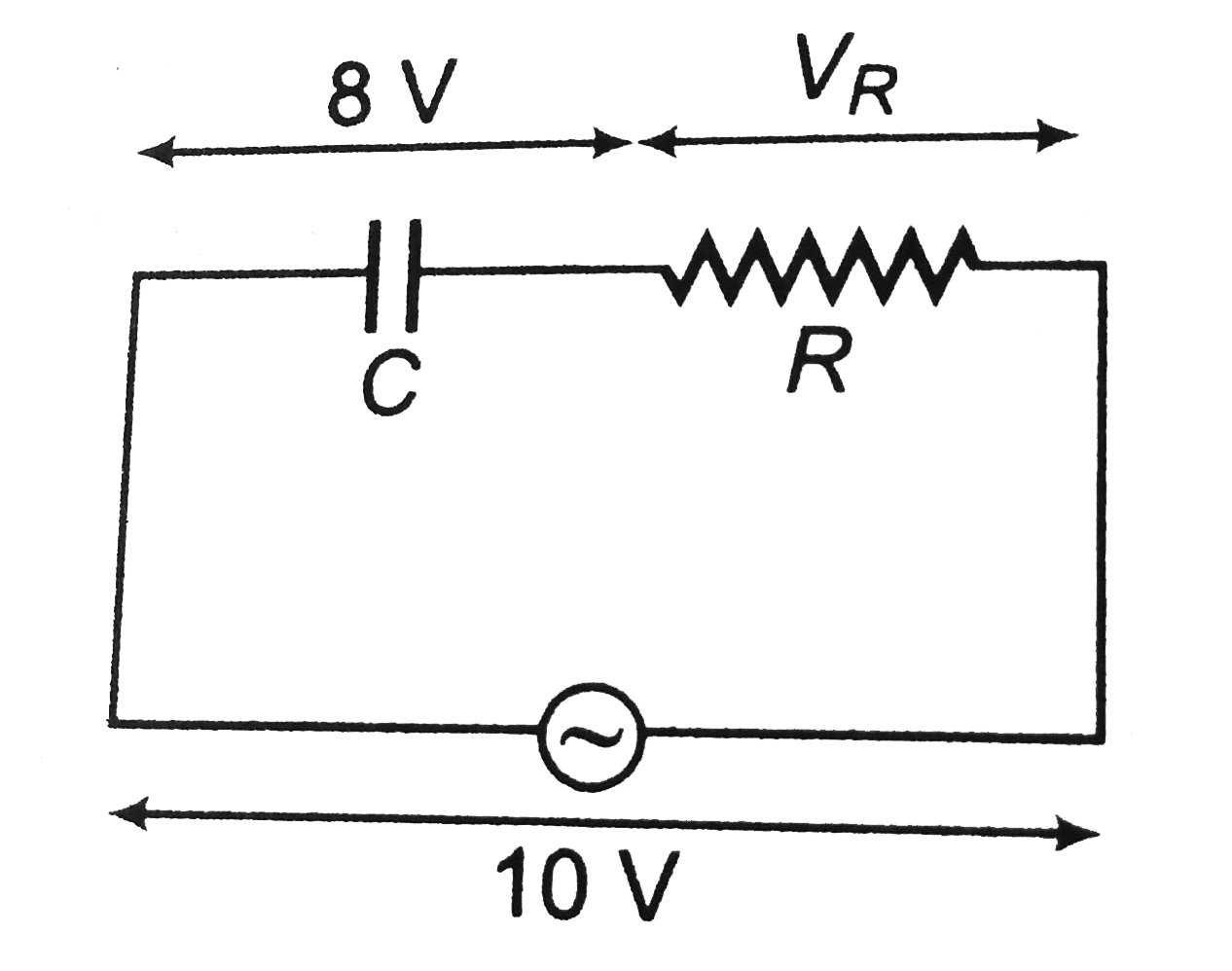 .A6V,tan−1(43)B3V,tan−1(34)C6V,tan−1(34)Dnone of these
A series L-C-R circuit is operated at resonance . Then
Avoltage across R is minimumBimpedance is minimumCimpedance is maximumDcurrent amplitude is minimum
In series L-C-R circuit as shown in figure the voltage of the source is
View SolutionIn series L-C-R circuit as shown in figure the voltage of the source is

View SolutionIn series resonant circuit, at resonance the phase difference between the voltage across inductor and voltage across condenser is
View SolutionSTATEMENT-1: In a series LCR circuit at resonance, the voltage across the capacitor or inductor may be more than the applied voltage.
STATEMENT-2: At resonance in a series LCR circuit, the voltages across inductor and capacitor are out of phase.
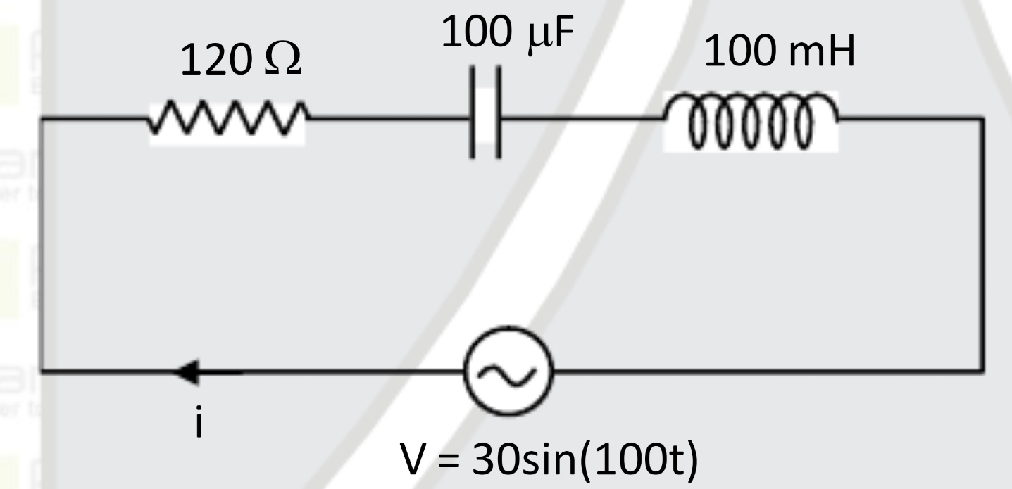
View SolutionIn a series L-C-R circuit shown in the figure , what is the resonance frequency and the current at the resonating frequency?
View Solution

