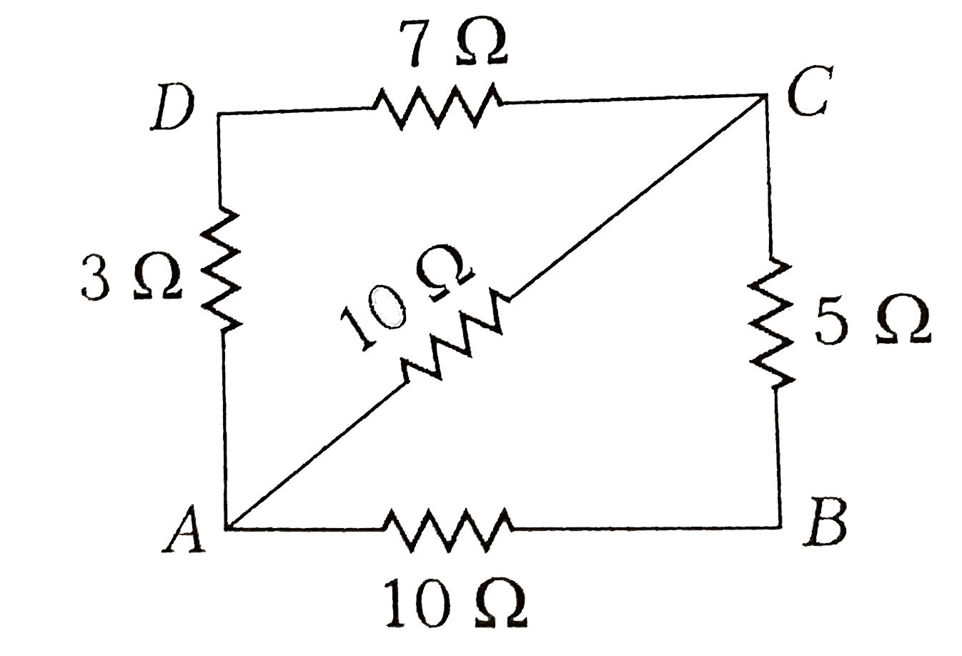
In the circuit shown in figure
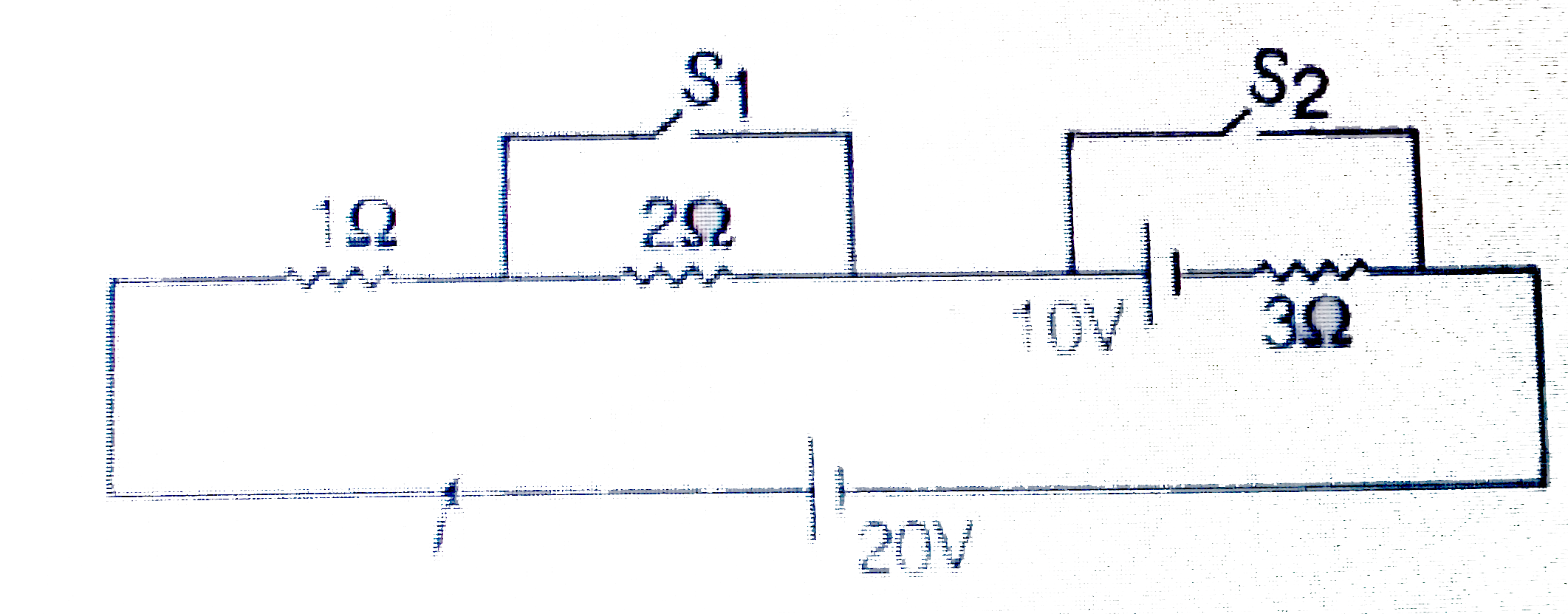
A) I=2.5A when S1 is closed and S2 is open
B) I=203A when S1 is open and S2 is closed
C) I=53A when S1 and both are open
D) I=20A when both S1 and S2 are closed
The correct Answer is:A, B, C, D
Step by step video & image solution for In the circuit shown in figure by Physics experts to help you in doubts & scoring excellent marks in Class 11 exams.
Updated on:21/07/2023Topper's Solved these Questions
Similar Questions
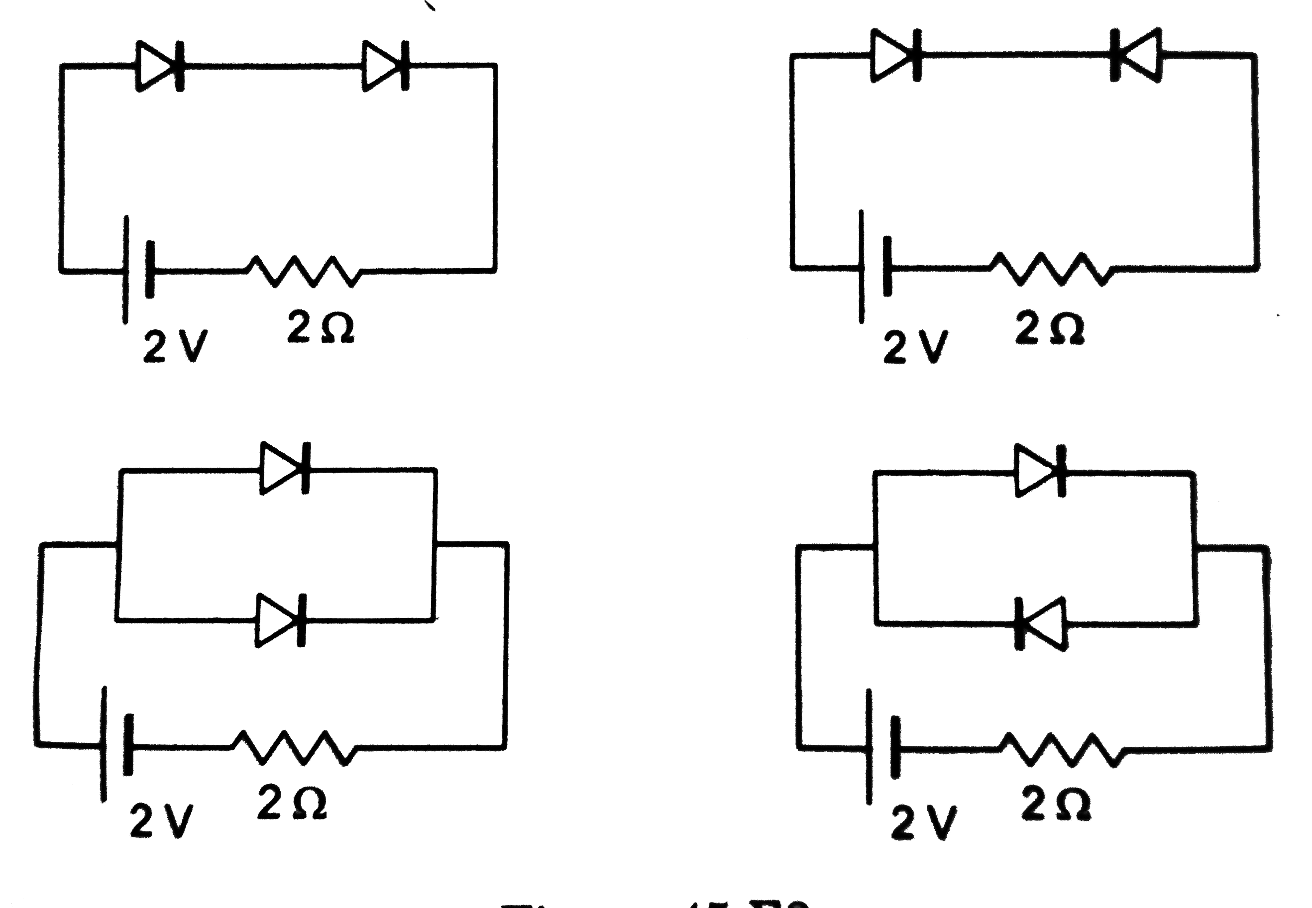
Find the current through the resistance in the circuits shown in figure
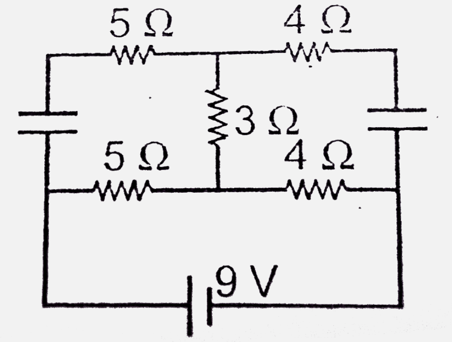
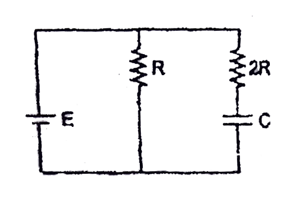
View SolutionThe power consumption by the circuit shown in figure at steady state is
View SolutionFor the circuit shown in figure, the equivalent capacitance of the combination is
View SolutionThe time constant of charging of the circuit shown in figure is
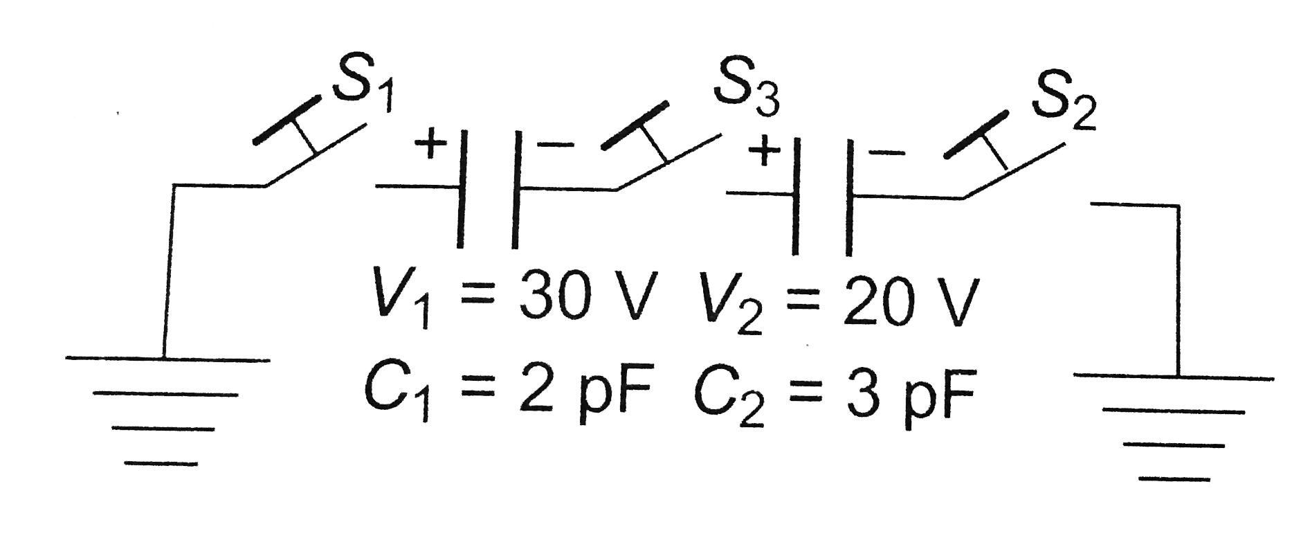
View SolutionFor the circuit shown in figure, which of the following statements is true ?
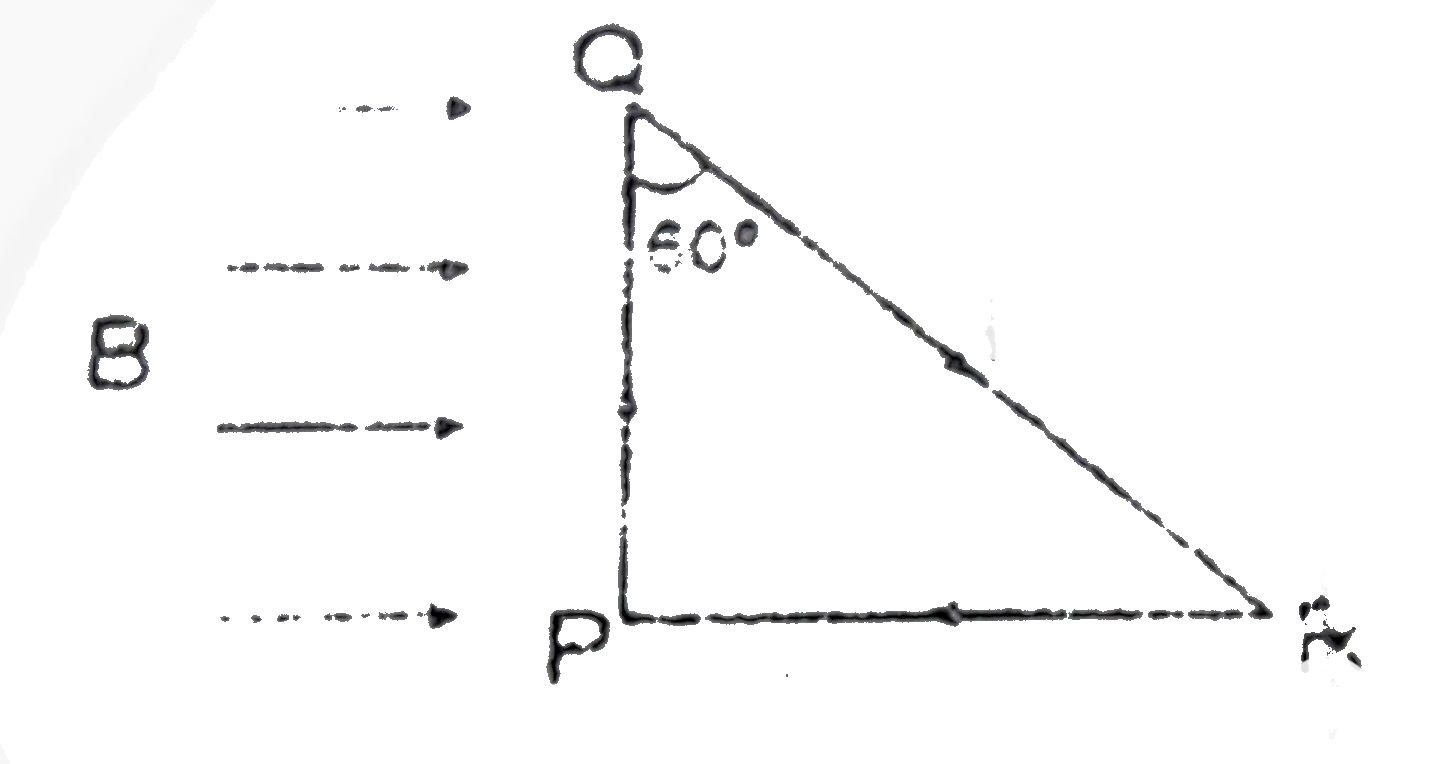
View SolutionFor the circuit shown in figure the direction and magnitude of the force on PQR is :
View SolutionTo get an output 1 from the circuit shown in figure the input must be :

View SolutionFor the circuit shown in figure, select the correct statements from the following options :
 .
.
View SolutionTo get an output of 1 form the circuit shown in figure the input must be :-
_E01_514_Q01.png)
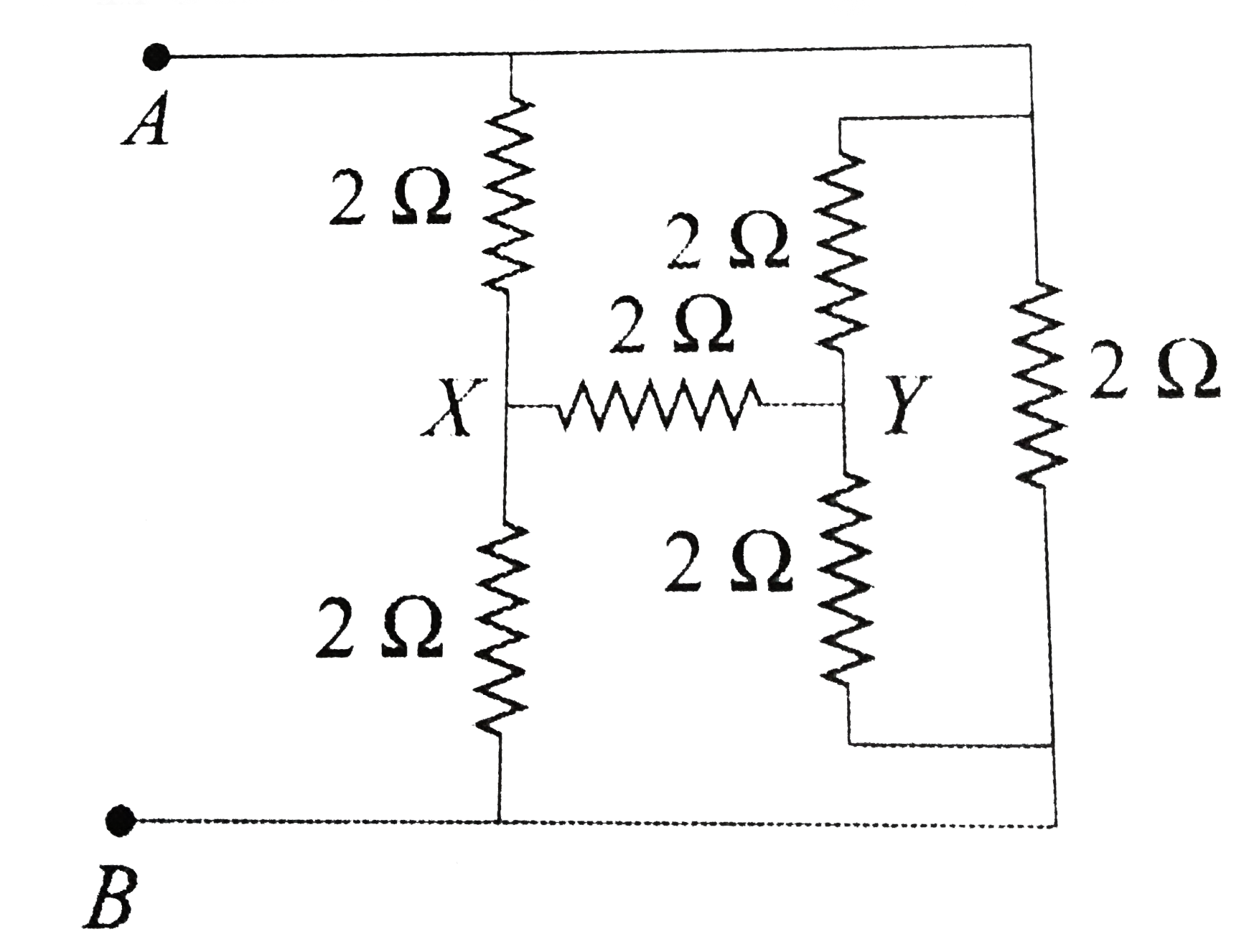
View SolutionFor the circuit shown in figure given below, the equivalent resistance points A and B is
View Solution
