In the circuit shown in figure , R1=R2=R3=R. Match the following
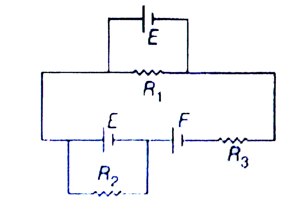
The correct Answer is:(A)P,(B)P,(C)P,
Step by step video & image solution for In the circuit shown in figure , R_(1)=R_(2)=R_(3)=R. Match the following by Physics experts to help you in doubts & scoring excellent marks in Class 11 exams.
Updated on:21/07/2023Topper's Solved these Questions
Similar Questions
In the L-C-R circuit as shown in figure,
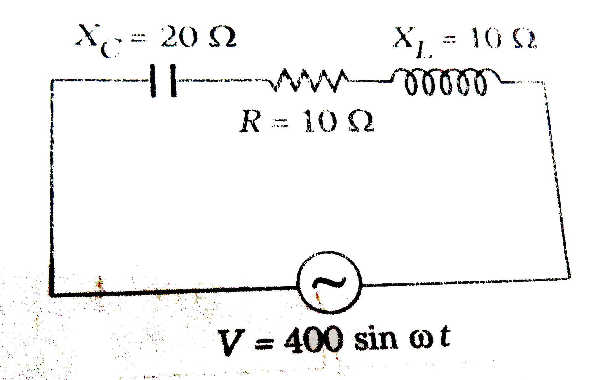
View SolutionIn the circuit shown in figure value of VR is
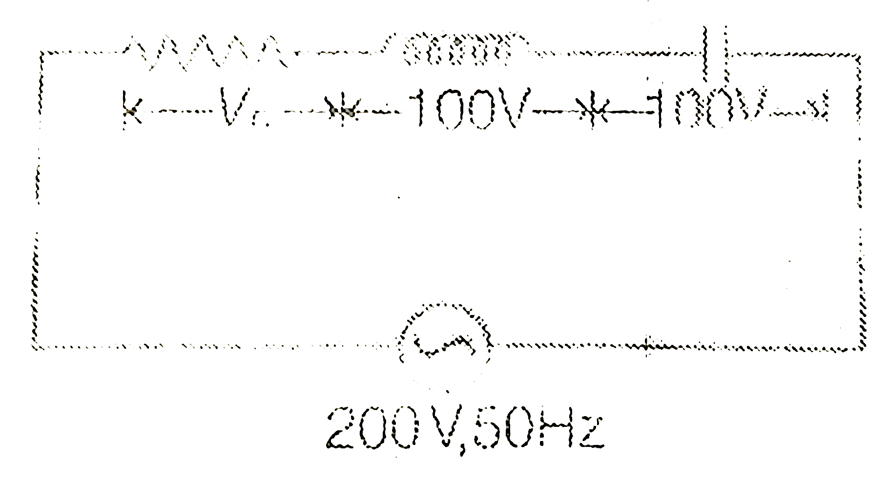
View SolutionFind RAB in the circuit shown in figure.
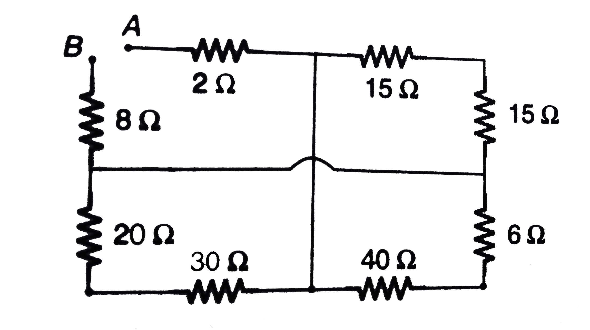
View SolutionThe potential difference in volt across the resistance R3 in the circuit shown in figure, is (R1=15Ω,R2=15Ω,R3=30Ω,R4=35Ω)
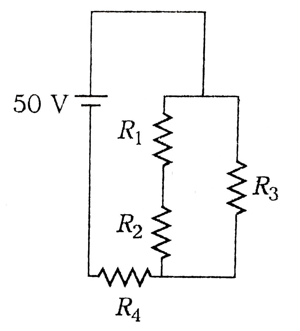
View SolutionIn the curcuit shown in figure R1=R2=R3=10Ω. Find the currents through R1 and R2
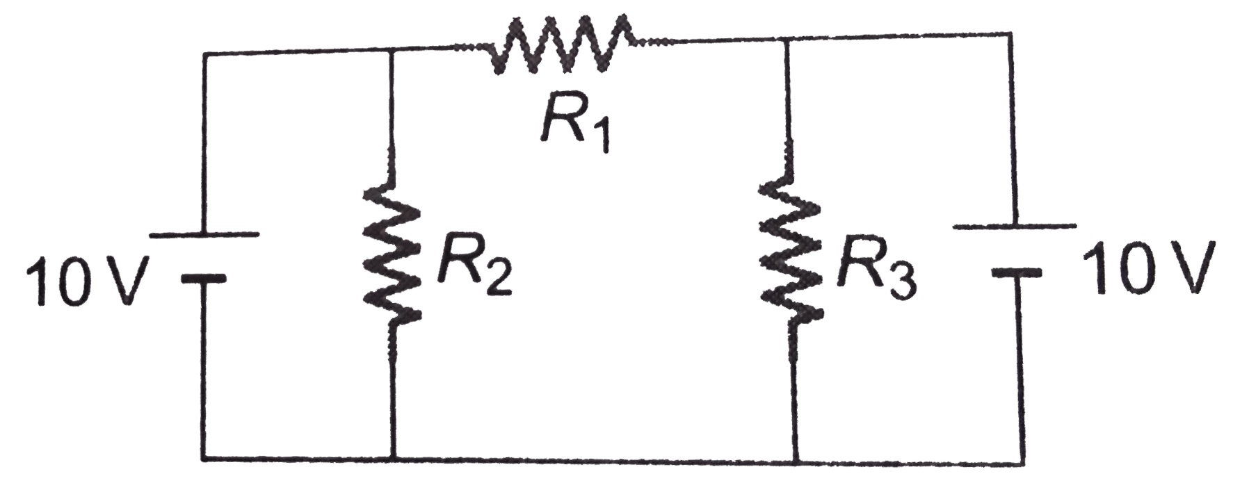
View SolutionIn the circuit shown in figure R1=R2=10Ω,E1=20V,E2=40V. For what value of R, the thermal power developed in it will be maximum (in Ω)?

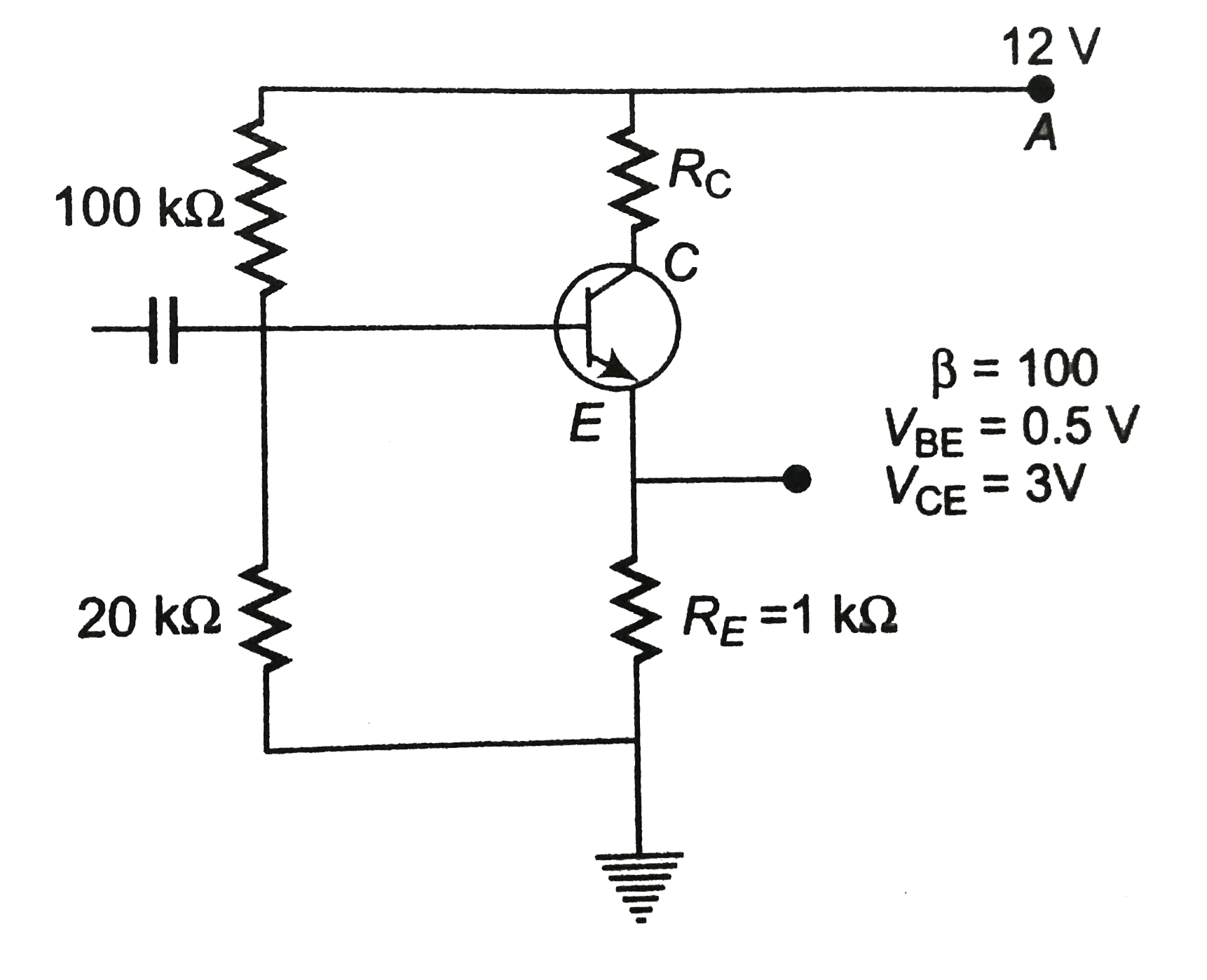
View SolutionIn the circuit shown in figure , find the value of RC.
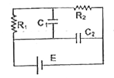
View SolutionIn the circuit shown in figure, R(1)=1Ω,R2=2Ω,C1=1μF,C2=2μF and E=6V. Calculate charge on each capacitor in steady state
View SolutionIn the circuit shown in figure
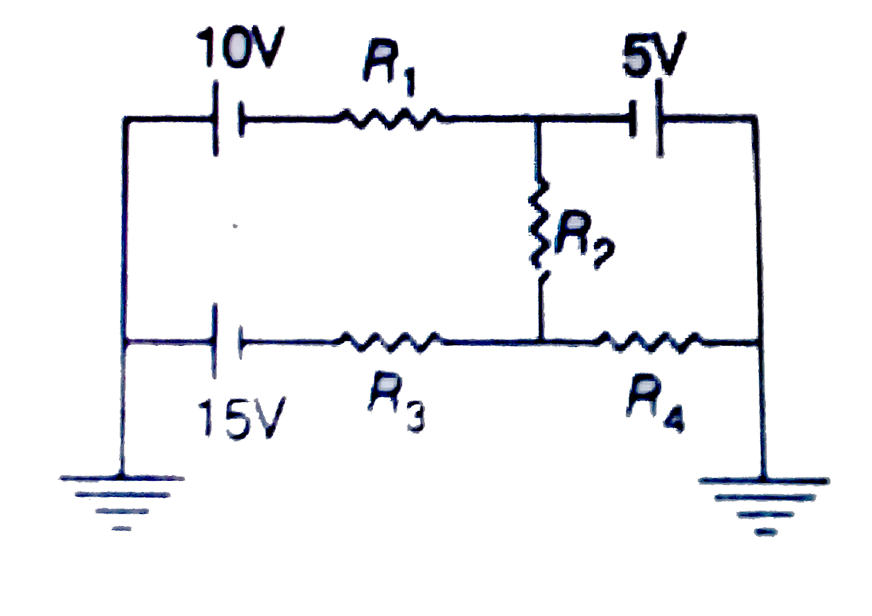
For what ratio R2R4, current through R3 will be zero
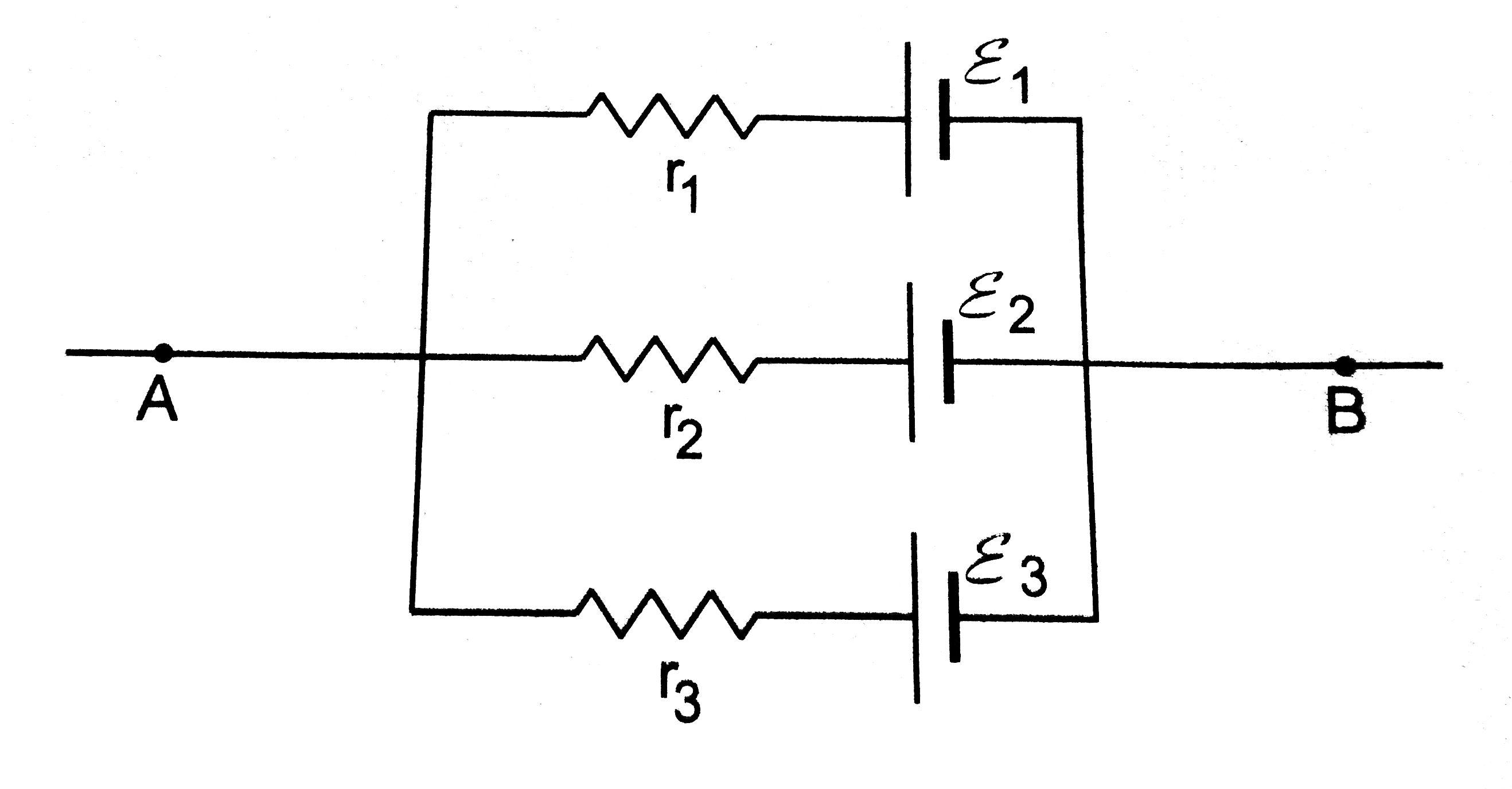
View SolutionIn the circuit shown in figure ,(ε)1=3V,(ε)2=2V,(ε)3=1Vandr1=r2=r3=1(Ω).Find the potential difference between the points A and B and the current through each branch.
View Solution
