The potential difference in volt across the resistance R3 in the circuit shown in figure, is (R1=15Ω,R2=15Ω,R3=30Ω,R4=35Ω)
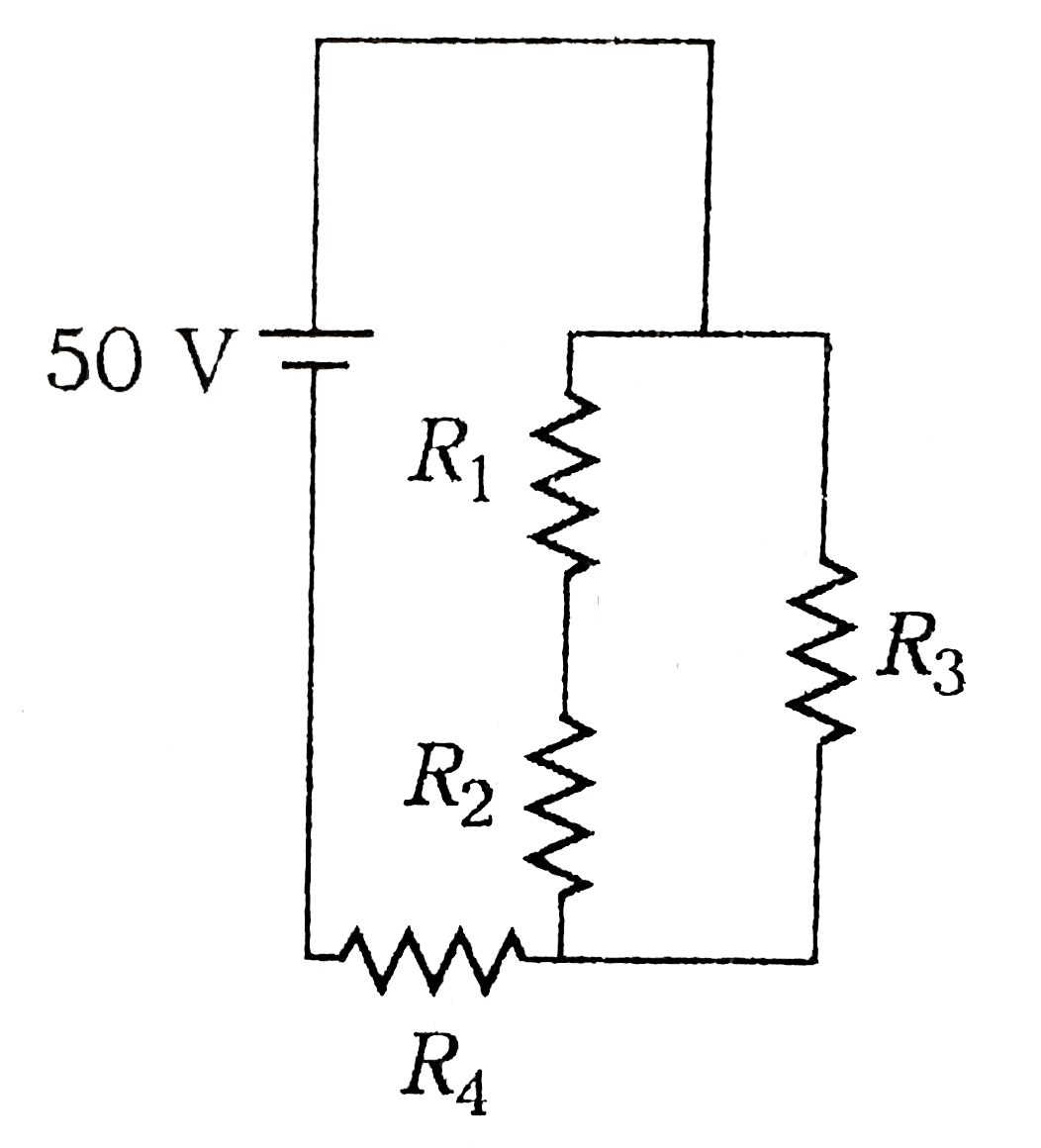
5
7.5
15
12.5
The correct Answer is:C
Step by step video & image solution for The potential difference in volt across the resistance R_(3) in the circuit shown in figure, is (R_(1)=15Omega,R_(2)=15Omega, R_(3)=30Omega, R_(4)=35Omega) by Physics experts to help you in doubts & scoring excellent marks in Class 12 exams.
Updated on:21/07/2023Topper's Solved these Questions
- CURRENT ELECTRICITYBOOK - DC PANDEY ENGLISHCHAPTER - CURRENT ELECTRICITYEXERCISE - B. Assertion and reason
18 Videos
- CURRENT ELECTRICITYBOOK - DC PANDEY ENGLISHCHAPTER - CURRENT ELECTRICITYEXERCISE - Match the columns
4 Videos
- CURRENT ELECTRICITYBOOK - DC PANDEY ENGLISHCHAPTER - CURRENT ELECTRICITYEXERCISE - Check point
70 Videos
- COMMUNICATION SYSTEMBOOK - DC PANDEY ENGLISHCHAPTER - COMMUNICATION SYSTEMEXERCISE - Subjective
11 Videos
- ELECTROMAGNETIC INDUCTIONBOOK - DC PANDEY ENGLISHCHAPTER - ELECTROMAGNETIC INDUCTIONEXERCISE - Medical entrances gallery
25 Videos
Similar Questions
Determine the voltage drop across the resistor R1 in the circuit given below with E=65V,R1=50Ω,R2=100Ω,R3=100Ω and R4300Ω

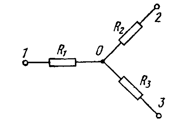
View SolutionFind the current flowing through the resistance R1 of the circuit shown in Fig. If the resistances are equal to R1=10Ω.R2=20Ω and R3=30Ω, and the potential of points 1,2 and 3 are equal to φ1=10V,φ2=6V, and φ3=5V
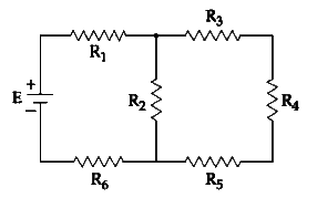
View SolutionIn the figure shown, what is the current (in Ampere) drawn from the battery ? You are given:
R1=15Ω,R2=10Ω,R3=20Ω,R4=5Ω,
R5=25Ω,R6=30Ω,E=15V
View SolutionPassage :
A battery EA of 123 volts emf internal resistance 0.4Ω and a battery EB of 117 V emf and internal resistance 0.6Ω supplies a current to load resistance RL through four wires of resistors RA=1.2Ω,RB=1Ω,RC=1.4ΩandRD=1.4Ω as shown in figure.
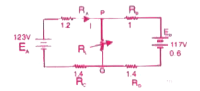
The value of load resistance for maximum load power is
View SolutionCurrent through resistor R3 as shown in figure is ______. Given that R1=10Ω R2=5Ω R4=20Ω and R5=10Ω

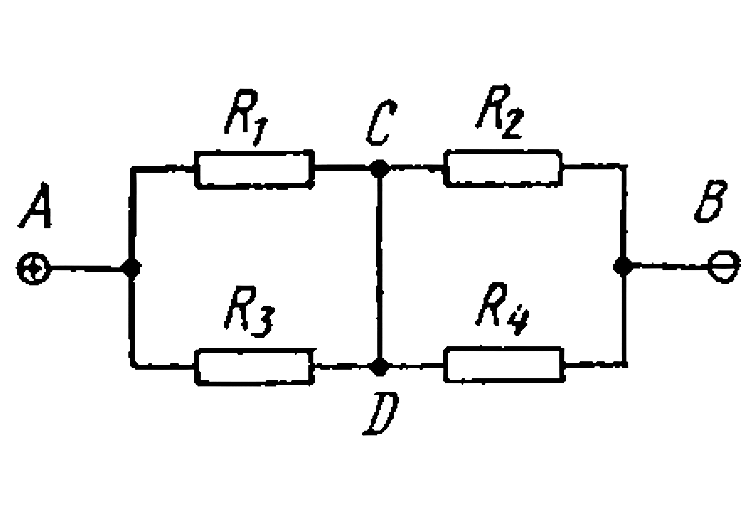
View SolutionA constant voltage V=25V is maintained between points A and B of the circuit (Fig). Find the magnitude and direction of the current flowing through the segment CD if the resistances are equal to R1=1.0Ω,R2=2.0Ω,R3=3.0Ω and R4=4.0Ω.
View SolutionThe power dissipated in the circuit shown in the figure is 30 W. The value of R is
View Solution(a) Resistors given as R1,R2andR3 are connected in series to a battery V. Draw the circuit diagram showing the arrangement. Derive an expression for the equivalent resistance of the combination.
(b) If R1=10Ω,R2=20ΩandR3=30Ω, calculate the effective resistance when they are connected in series to a battery of 6 V. Also find the current flowing in the circuit.
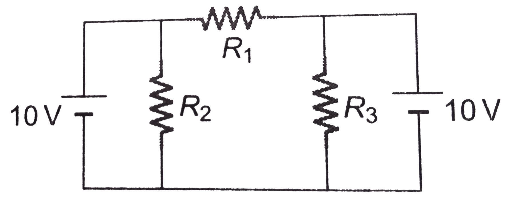
View SolutionIn the curcuit shown in figure R1=R2=R3=10Ω. Find the currents through R1 and R2
View SolutionIn the circuit shown in figure
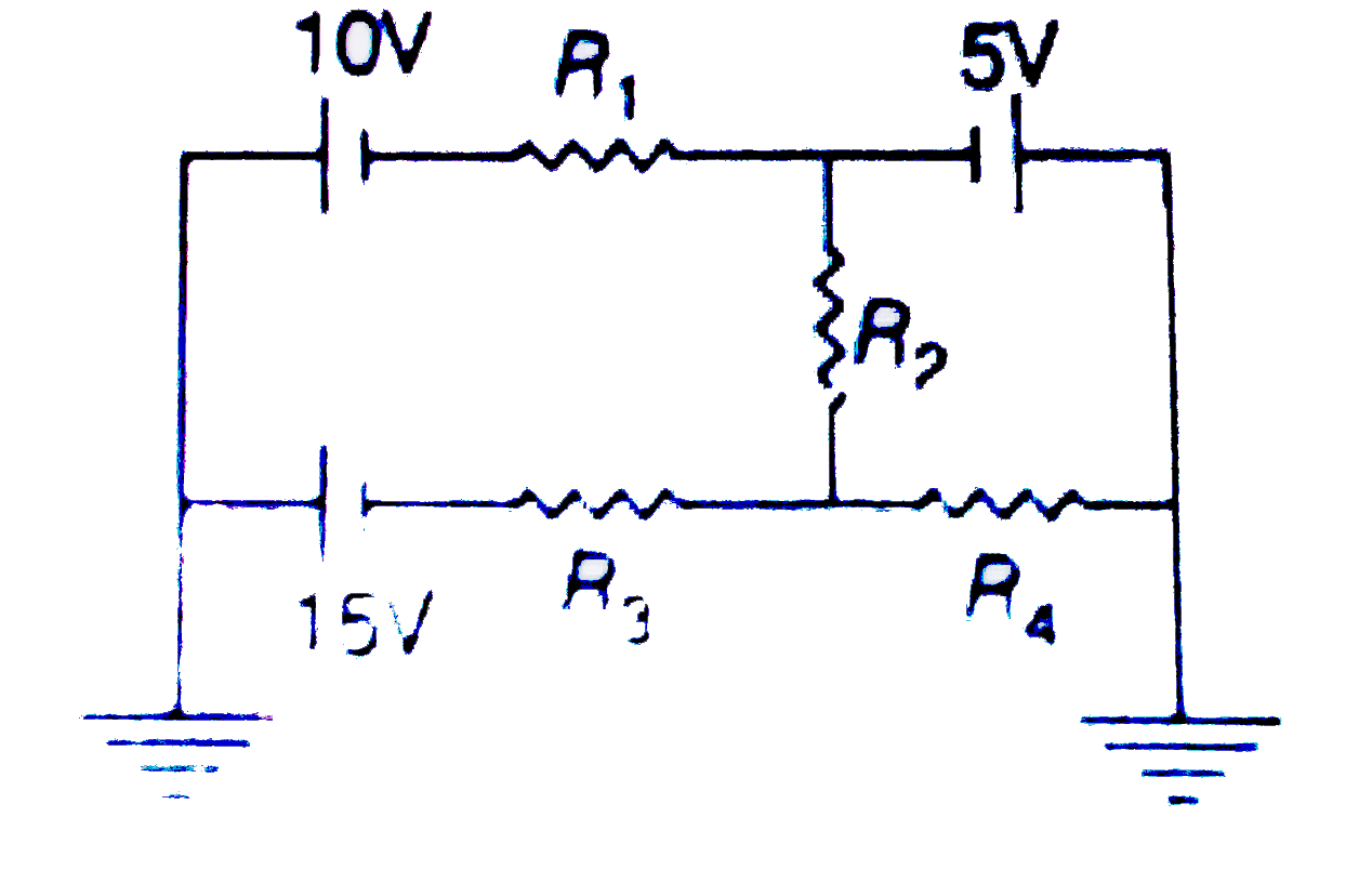
Current through R2 is zero if R4=2Ω and R3=4Ω In this case
View Solution
