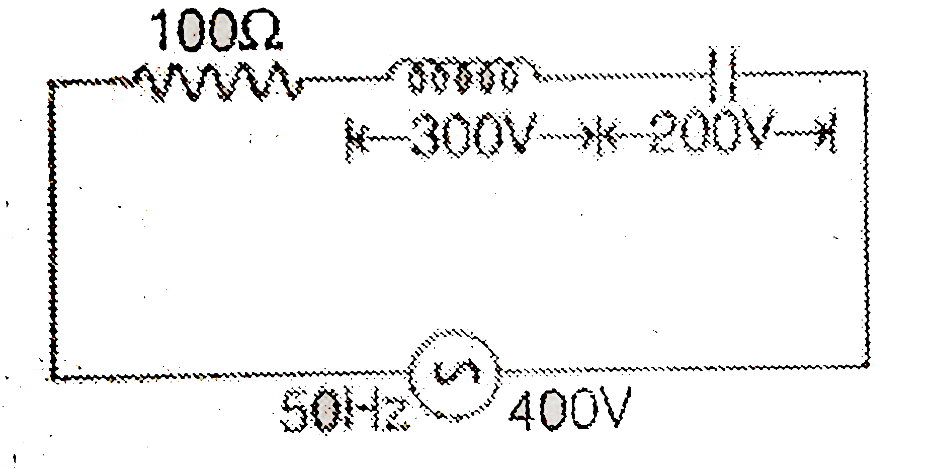
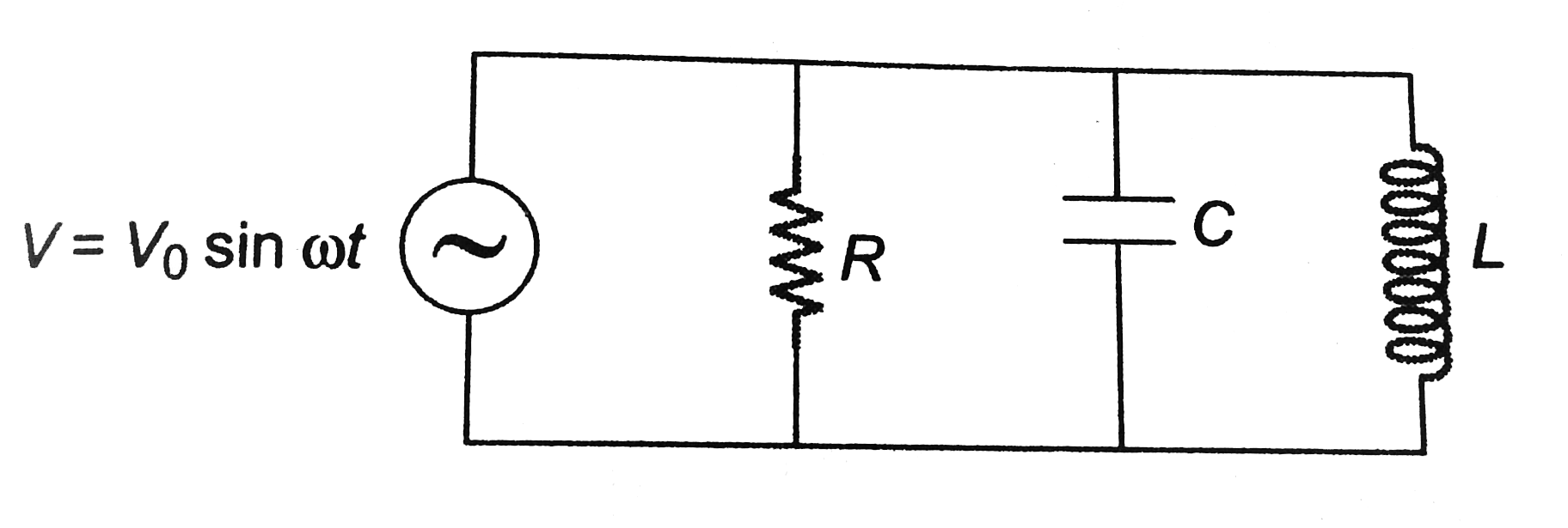
In the circuit shown in figureure,
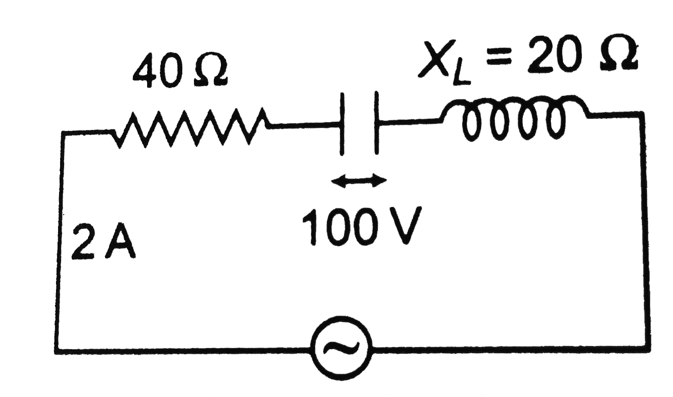 .
.
A
VR=80V
B
XC=50Ω
C
VL=40V
D
V0=100V
Video Solution
Text Solution
The correct Answer is:A, B, C
(a) VR=IR=80V
(b) XC=VCI=1002=50Ω
(c) VL=IXL=40V
(d) V=Vrms=√V2R+(VC−VL)2
=√(80)2+(100−40)2
=60V
∴V0=√2Vrms=60√2V
|
Updated on:21/07/2023
Topper's Solved these Questions
- BOOK - DC PANDEYCHAPTER - ALTERNATING CURRENTEXERCISE - Level 2 Comprehension6videos
ALTERNATING CURRENT
- BOOK - DC PANDEYCHAPTER - ALTERNATING CURRENTEXERCISE - Level 2 Subjective10videos
ALTERNATING CURRENT
- BOOK - DC PANDEYCHAPTER - ALTERNATING CURRENTEXERCISE - Level- 2 Single Correct18videos
ALTERNATING CURRENT
- BOOK - DC PANDEYCHAPTER - ATOMSEXERCISE - MEDICAL ENTRANCES GALLERY42videos
ATOMS
Similar Questions
Knowledge Check
- Question 1 - Select One
For the circuit shown in figure,
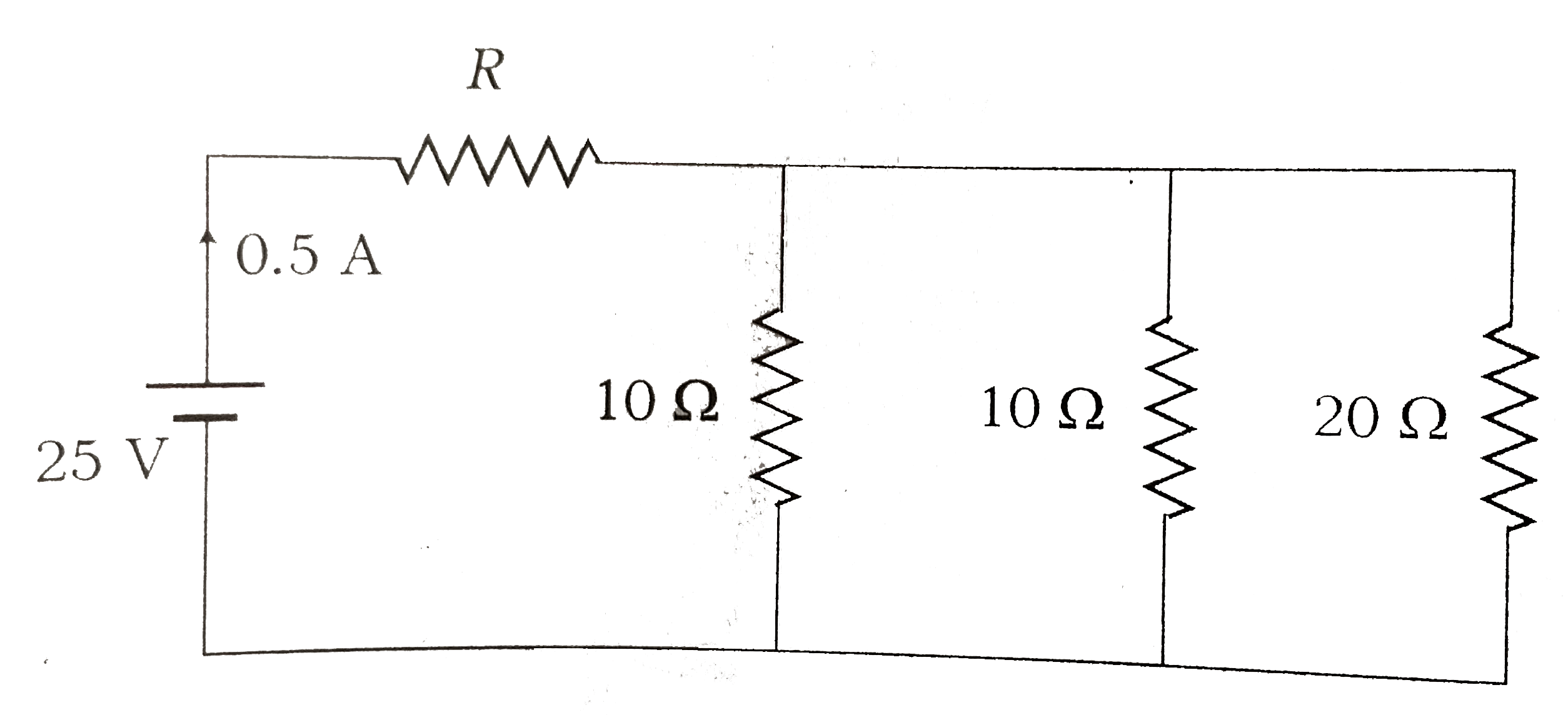 Aresistance R=46ΩBcurrent through 20Ω resistance is 0.1ACpotential difference across the middle resistance is 2 VDAll of the above are true
 - Question 2 - Select One or More
For the circuit shown in figure
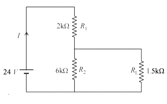 Athe current I through the batter is 7.5 mA.Bthe potential difference across R_L is 18V.Cratio of powers dissipated in R1andR2 is 3Dif R1andR2 are interchanged, magnitude of the power dissipated in RL will decrease by a factor of 9.
 - Question 3 - Select One
In the circuit shown in figure current in the circuit is
 A1.27AB2.23AC4.26AD4 A
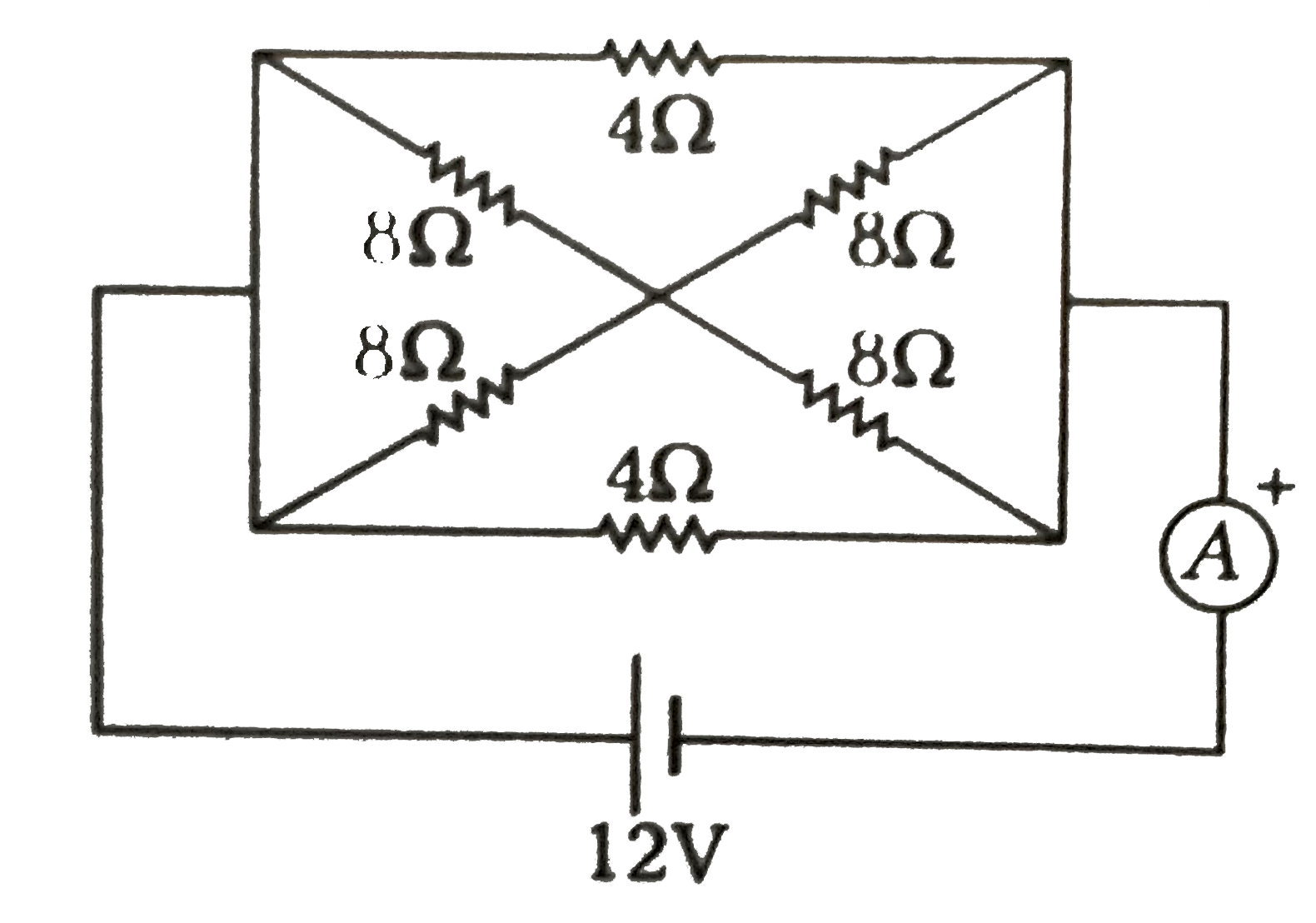
Calculate the current shown by the ammeter A in the circuit shown in figure.
 View Solution
Draw the circuit diagram to represent the circuit shown infigure.
 View Solution
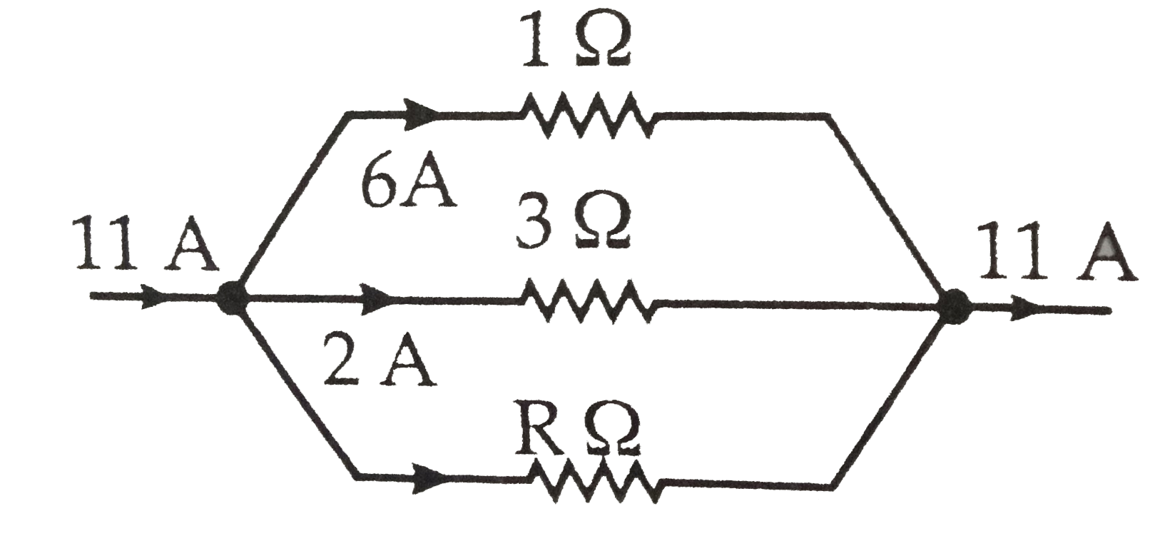
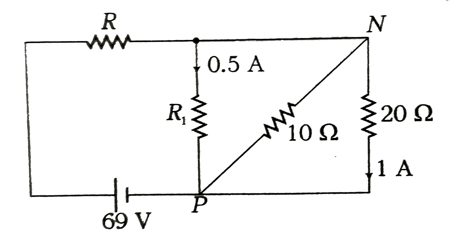
In the circuit shown in the figure,
 View Solution
In the circuit shown in figure, the ratio
 View Solution
In the circuit shown in figure , V must be
 View Solution


 .
.