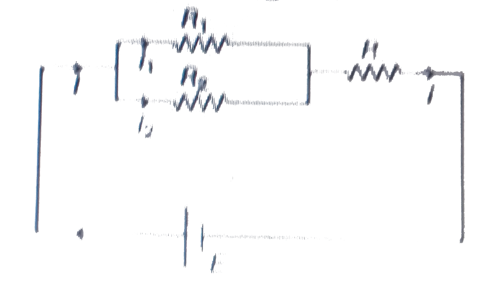
In the circuit shown in figure, the value of R is
A
1Ω
B
2Ω
C
3Ω
D
4Ω
Video Solution
Text Solution
The correct Answer is:B
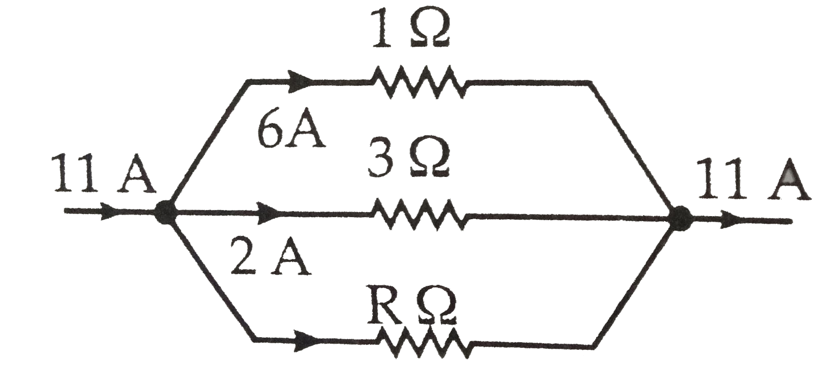
R1=1Ω,R2=2Ω,R3=Rω,I1=6A,I2=2A,R=?
From figure, I3=11−8=3A
Now in figureR1,R2 and R3 are in parallel.
∴V=I1R1=I3R3
∴R3=I1R1I3=6×13
R3=R=2Ω
|
Topper's Solved these Questions
- CURRENT ELECTRICITYBOOK - NIKITA PUBLICATIONCHAPTER - CURRENT ELECTRICITYEXERCISE - Multiple Choice Questions
314 Videos
- COMMUNICATION SYSTEMSBOOK - NIKITA PUBLICATIONCHAPTER - COMMUNICATION SYSTEMSEXERCISE - Multiple Choice Questions (Examples for Practice)
8 Videos
- ELASTICITYBOOK - NIKITA PUBLICATIONCHAPTER - ELASTICITYEXERCISE - MCQ
314 Videos
Similar Questions
Knowledge Check
In the circuit as shown in figure the
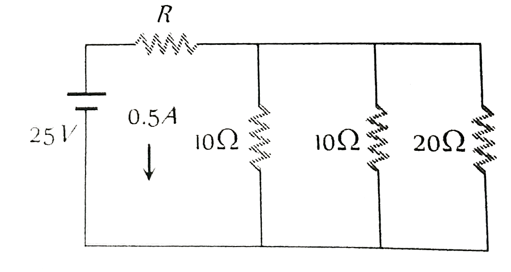 AResistance R=46ΩBCurrent through 20Ω resistance is 0.1ACPotential difference across the middle resistance is 2VDAll option are correct
For the circuit shown in figure,
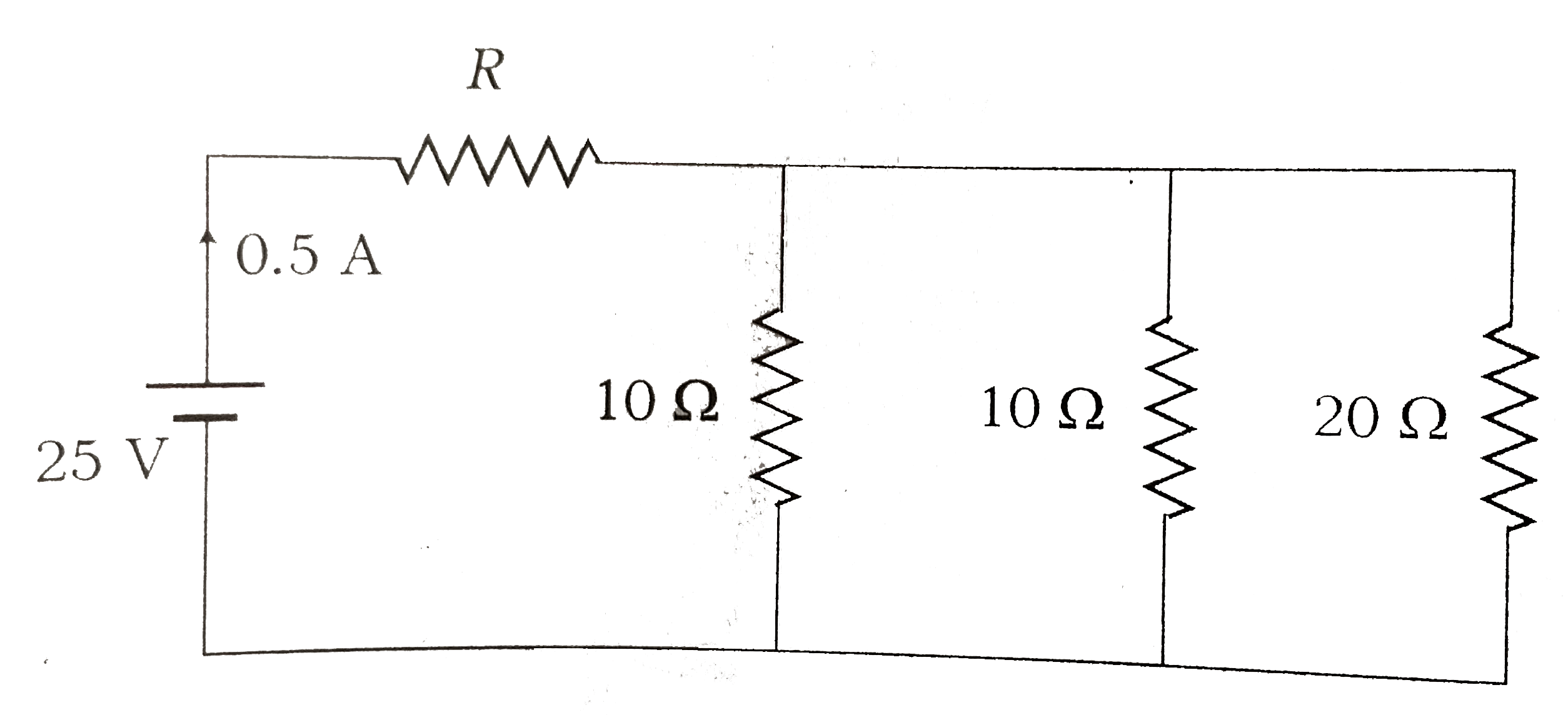 Aresistance R=46ΩBcurrent through 20Ω resistance is 0.1ACpotential difference across the middle resistance is 2 VDAll of the above are true
In the circuit shown in figure value of VR is
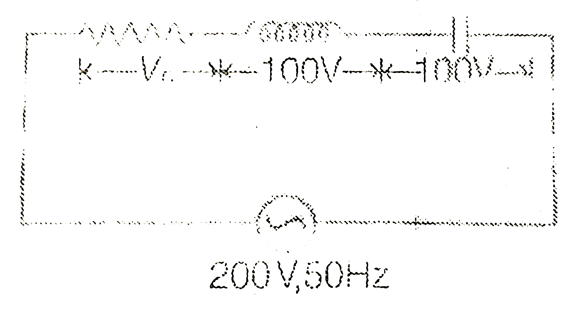 A400VB200VC300VDzero
In the circuit shown in the figure,
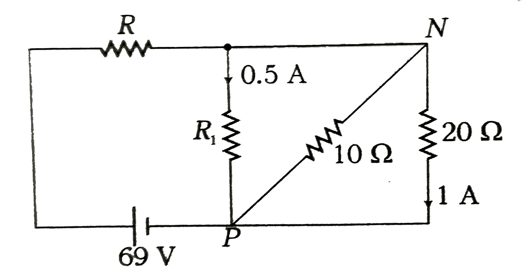
View SolutionIn the circuit shown in the figure, the value of maximum rate of heat production in resistance R is
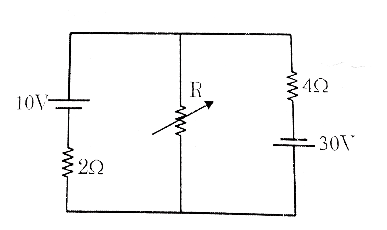
View SolutionIn the two circuits shown in figure
View SolutionIn the circuit shown in the figure
 .
.
View SolutionIn the diode circuit shown in figure,

View Solution

