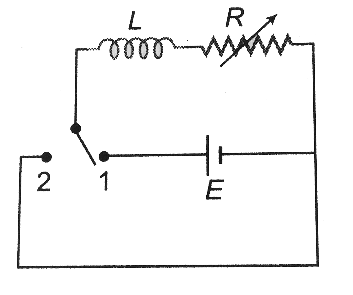
In the circuit shown in the figure initialy the switch in position 1 for a long time, then suddenly at t=0 the switch is shifted to position 2. It is required that a constant current should flow in the circuit, the value of resistance R in the circuit
should be decreased at constant ratee
should be increased at a constant rate
should be maintained constant
not possible
The correct Answer is:D
In decay of current though L−R circuit, current can not remain constant.
Topper's Solved these Questions
- BOOK - DC PANDEYCHAPTER - ELECTROMAGNETIC INDUCTIONEXERCISE - Level 2 More Than One Correct10videos
ELECTROMAGNETIC INDUCTION
- BOOK - DC PANDEYCHAPTER - ELECTROMAGNETIC INDUCTIONEXERCISE - Level 2 Comprehension Based13videos
ELECTROMAGNETIC INDUCTION
- BOOK - DC PANDEYCHAPTER - ELECTROMAGNETIC INDUCTIONEXERCISE - Level 1 Subjective21videos
ELECTROMAGNETIC INDUCTION
- BOOK - DC PANDEYCHAPTER - CURRENT ELECTRICITYEXERCISE - Medical entrances gallery97videos
CURRENT ELECTRICITY
- BOOK - DC PANDEYCHAPTER - ELECTROMAGNETIC WAVESEXERCISE - Sec C22videos
ELECTROMAGNETIC WAVES
Similar Questions
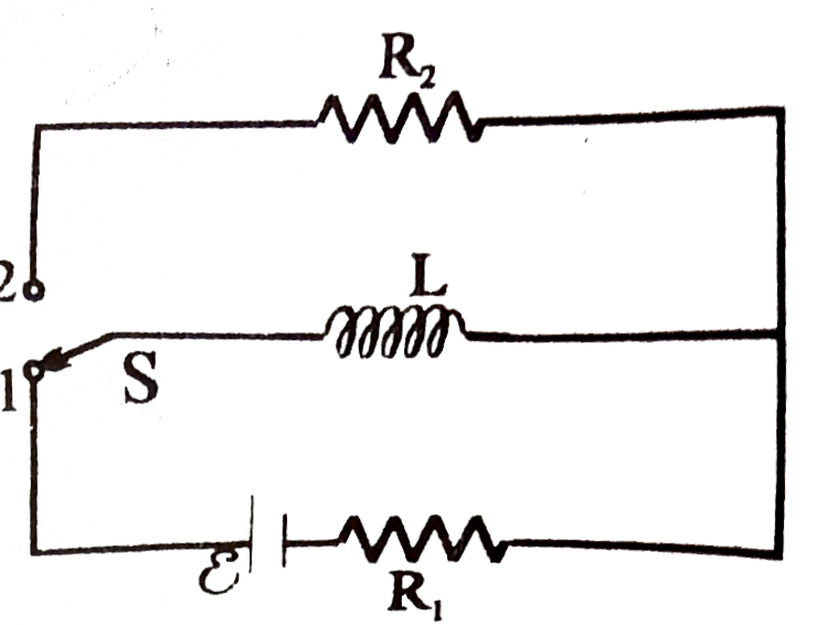
In the circuit shown, initially the switch is in position 1 for a long time. Then the switch is shifted to position 2 for a long time. Find the total heat produced in R2
 View Solution
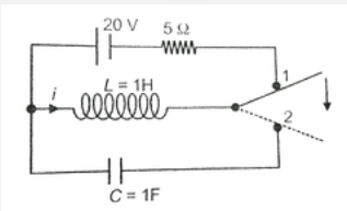
In the circuit shown, the switch has been in position 1 for a long time. Now the switch is shifted to position 2. If this instant is taken as t = 0, then at time t=π2
 View Solution
Knowledge Check
- Question 1 - Select One
In figure, the switch is in the position 1 for long time, then the switch is shifted to position 2 at t=0. At this instant the value of i1 and i2 are
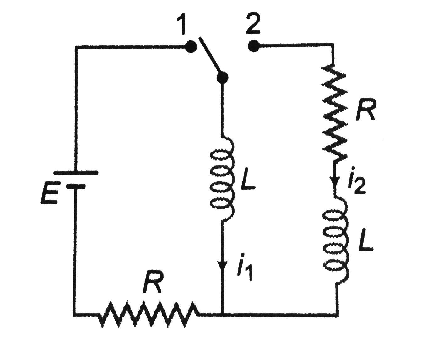 AER,0BER,−ERCE2R,−E2RDNone of these
 - Question 2 - Select One or More
In the circuit as shown in figure the switch is closed at t=0.
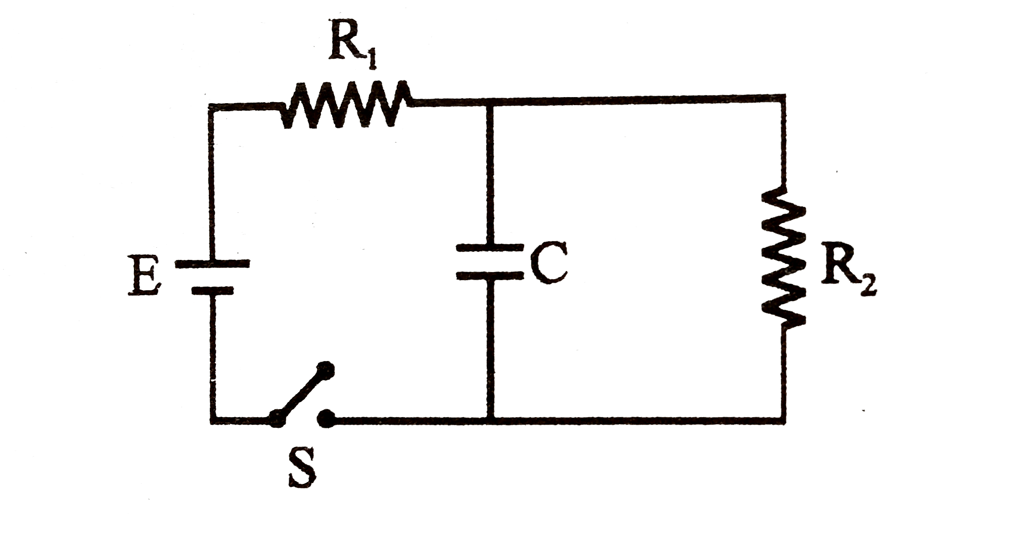
A long time after closing the switchAvoltage drop across the capacitor is EBcurent through the battery is E/R1+R2Cenegru stores in the capacitor is
12C(R2ER1+R2)2Dcurrent through the capacitor becomes zero - Question 3 - Select One
In the circuit as shown in the figure, switch S is added at t=0. Then:
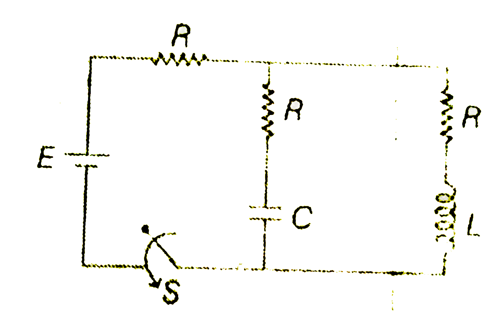 Aafter a long time interval potential differences across capacitor and inductor will be equalBafter a long time interval charge on a capacitor will be ECCafter a long time interval curent in the inductory will be E/RDafter a long time interval current through battery willl be same as the curren through it initially
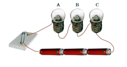
In the circuit shown in Fig. 12.3, when the switch is moved to ‘ON’ position
 View Solution
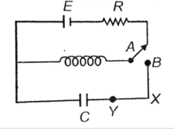
Switch is in position A for long time. At time t = 0 it is shifted to position B. Find the maximum charge that will accumulate on capacitor
 View Solution
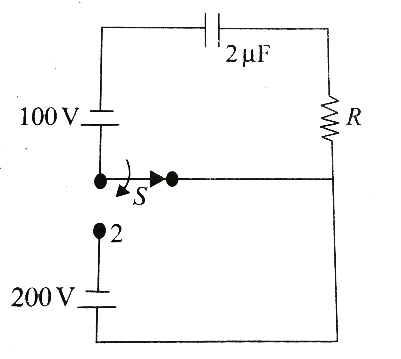
In the circuit shown in the figure, the switch S is in position 1 for a long time. Now the switch is thrown to position 2. Find the total heat developed in the circuit till the steady state is reached again.
 View Solution
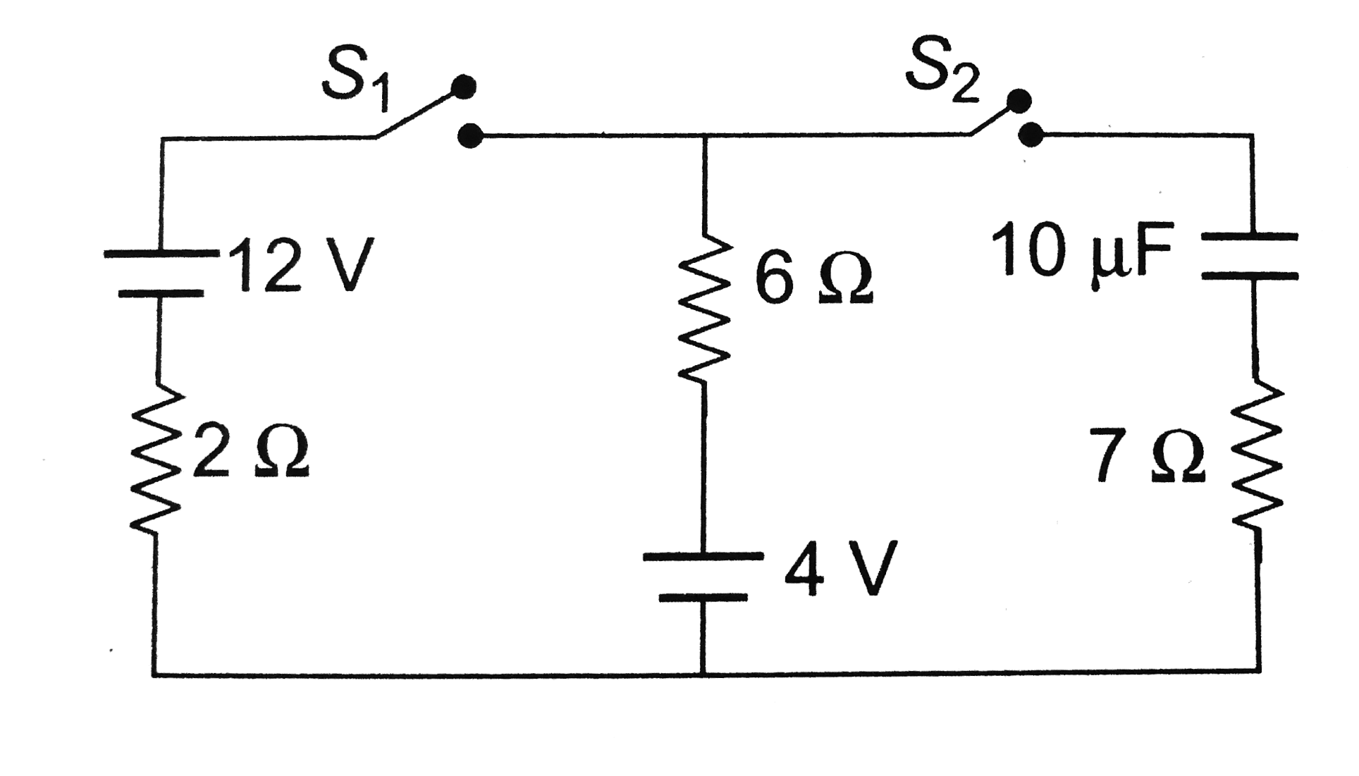
In the circuit shown in the figure, if switches S1 and S2 have been closed for a long time, then charge on the capacitor.
 View Solution
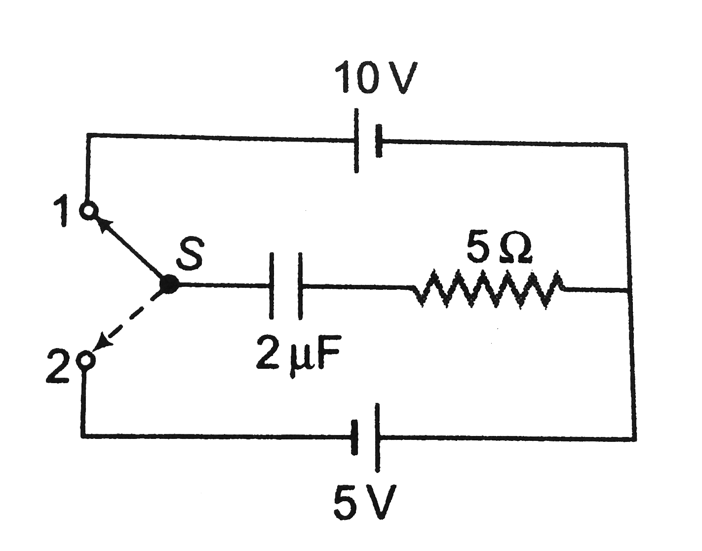
In the circuit shown in figure switch S is thrown to position 1 at t=0. when the current in the resistor is 1A, it is shifted to position 2. the total heat generated in the circuit after shifting to position 2 is
 View Solution

