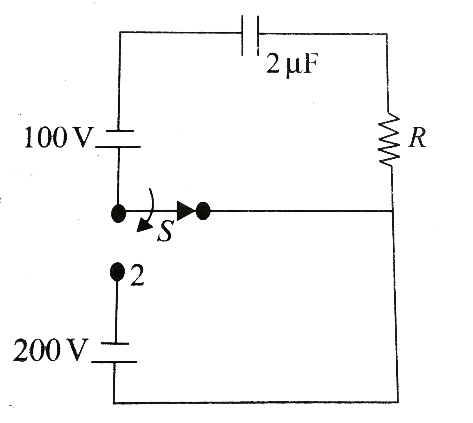
In the circuit shown in the figure, the switch S is in position 1 for a long time. Now the switch is thrown to position 2. Find the total heat developed in the circuit till the steady state is reached again.
0.04 J
0.4 J
0.02 J
0.2 J
The correct Answer is:A
a. Initial charge on capacitor : Q1=2×100=200μC
Final charges: Q2=2×300=600μC
Wb=300[Q2−Q1]=12,0000μJ
ΔU=12C[3002−1002]=80000μJ
Heat =Wb−ΔU=40000μJ=0.04J
Similar Questions
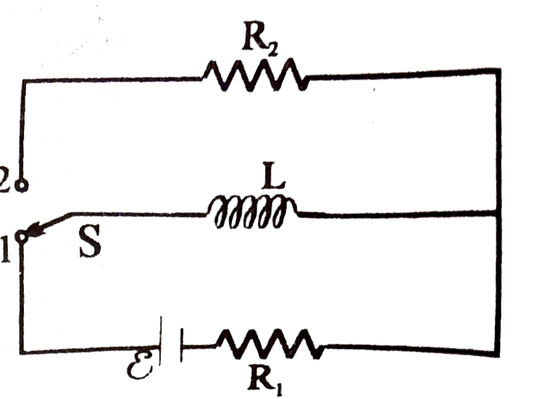
In the circuit shown, initially the switch is in position 1 for a long time. Then the switch is shifted to position 2 for a long time. Find the total heat produced in R2
 View Solution
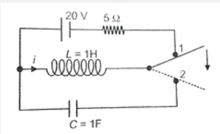
In the circuit shown, the switch has been in position 1 for a long time. Now the switch is shifted to position 2. If this instant is taken as t = 0, then at time t=π2
 View Solution
Knowledge Check
- Question 1 - Select One
In the circuit as shown in the figure, switch S is added at t=0. Then:
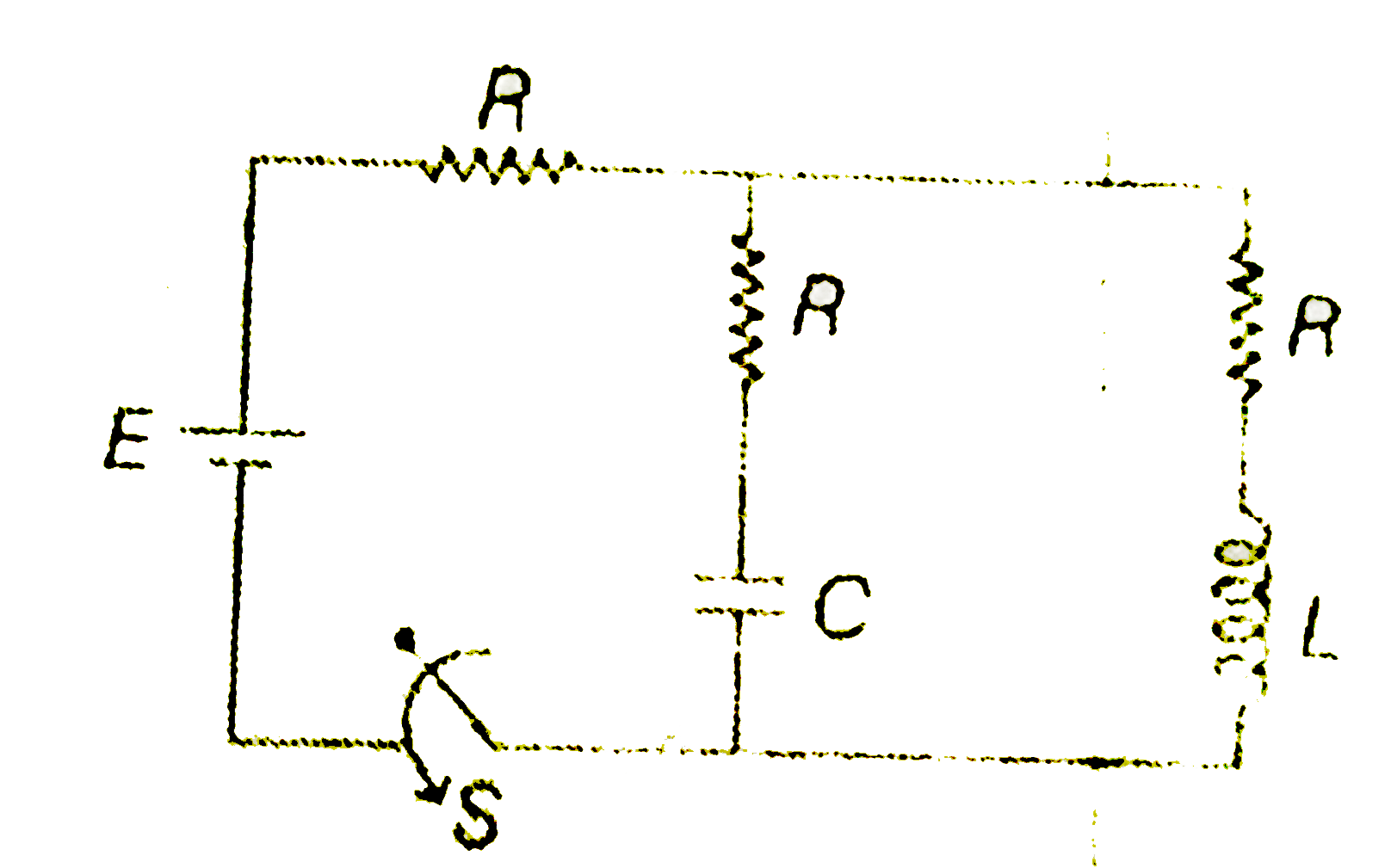 Aafter a long time interval potential differences across capacitor and inductor will be equalBafter a long time interval charge on a capacitor will be ECCafter a long time interval curent in the inductory will be E/RDafter a long time interval current through battery willl be same as the curren through it initially
 - Question 2 - Select One or More
In the circuit as shown in figure the switch is closed at t=0.
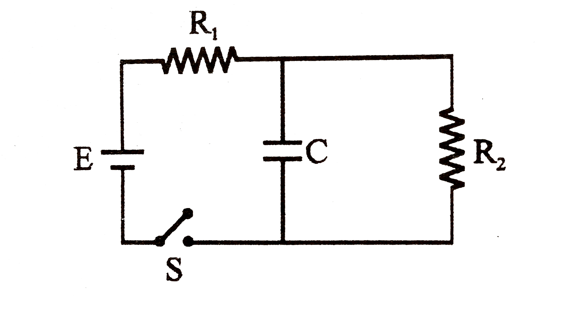
A long time after closing the switchAvoltage drop across the capacitor is EBcurent through the battery is E/R1+R2Cenegru stores in the capacitor is
12C(R2ER1+R2)2Dcurrent through the capacitor becomes zero - Question 3 - Select One
In the circuit shown in figure, switch S is initially closed and S is open. Find V-V
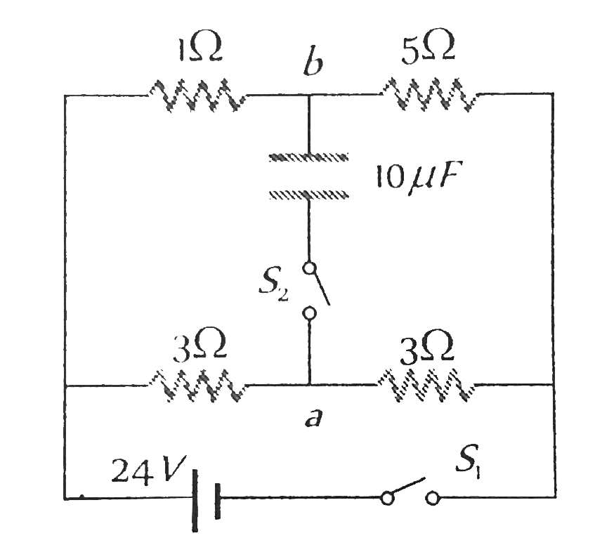 A4VB8VC12VD16V
In when the switch is swapped from 1 to 2, find the heat produced in the circuit.
 .View Solution
Consider the circuit shown in figure.

What is the current in the inductor at the instant the switch is thrown to position b?View SolutionIn the circuit shown below, the switch is in position 1 for a long time. At some moment after that the switch is thrown in position 2. The quantity of heat generated in the resistance of 375 ohm after the switch is changes to position 2 is :
 View Solution
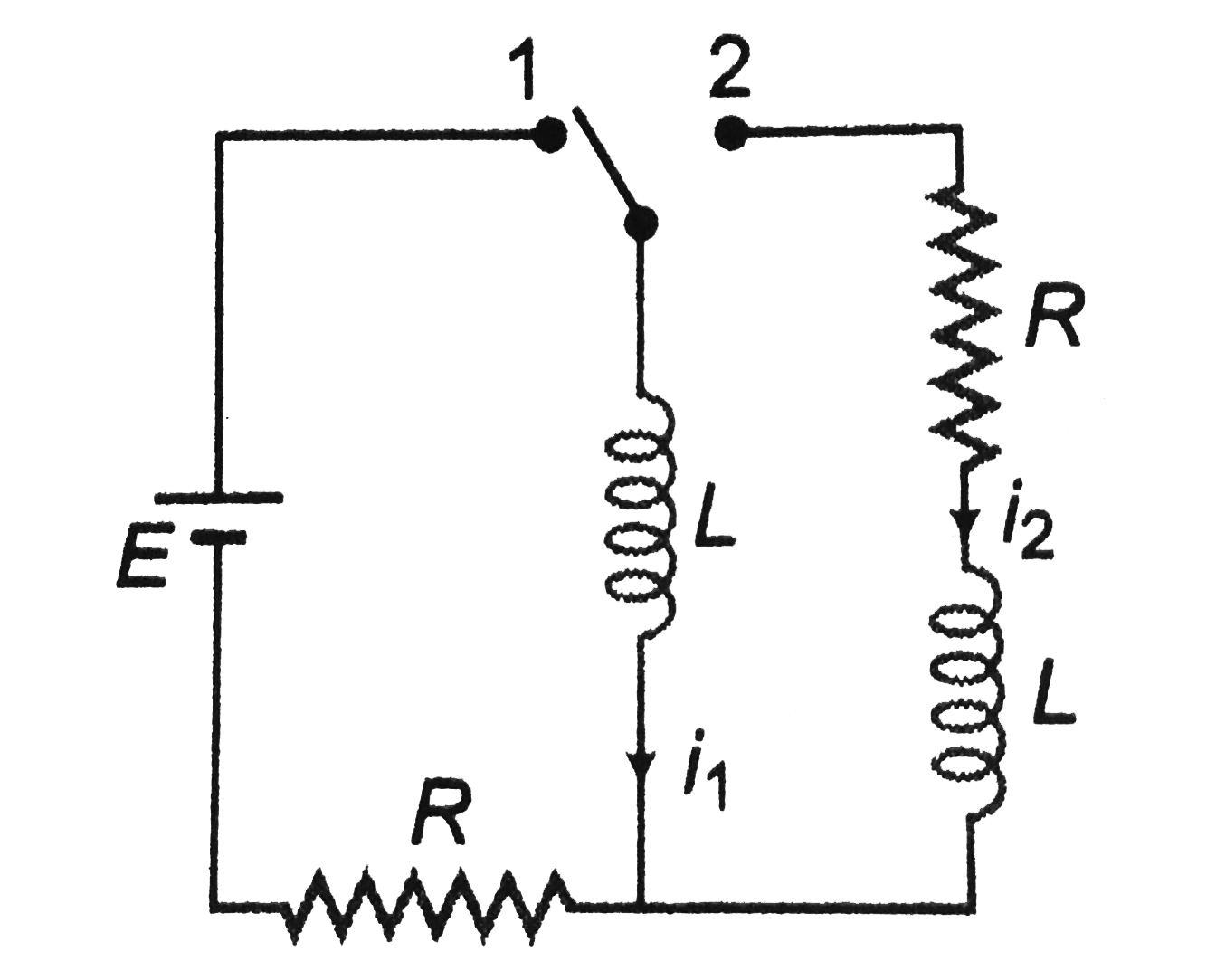
In figure, the switch is in the position 1 for long time, then the switch is shifted to position 2 at t=0. At this instant the value of i1 and i2 are
 View Solution
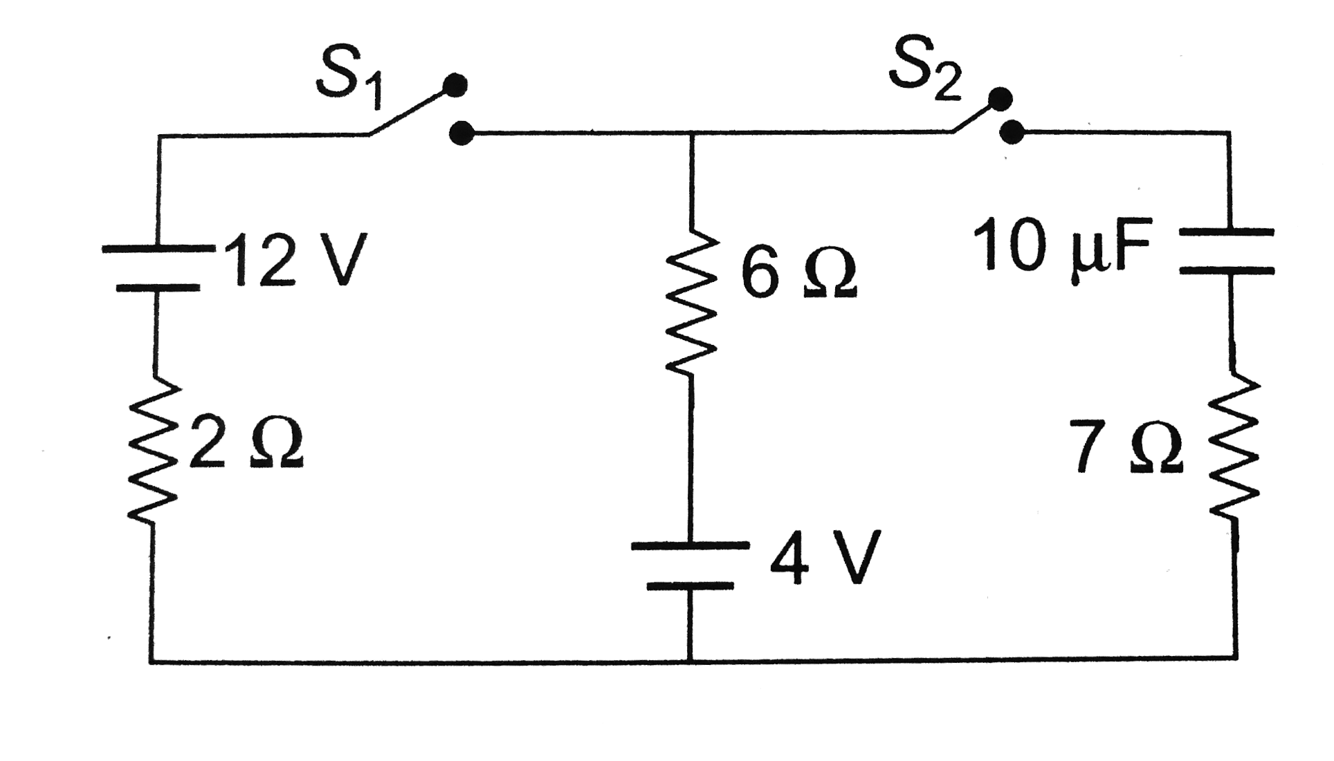
In the circuit shown in the figure, if switches S1 and S2 have been closed for a long time, then charge on the capacitor.
 View Solution

