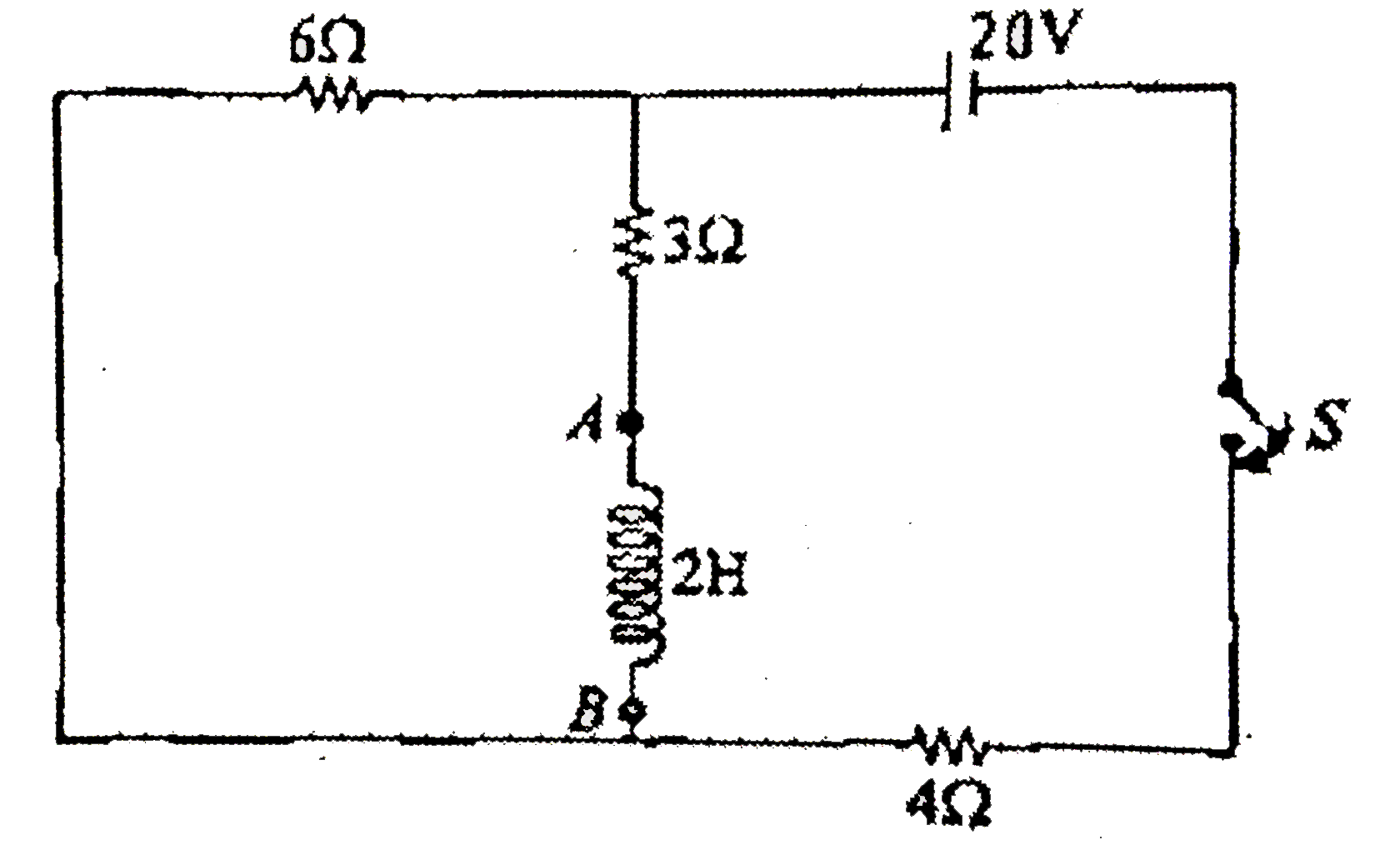
In the circuit shown in the figure. L is ideal inductor and E is ideal cell. Swictch S is Closed at , Then:

after a long time interval potential difference across capacitor and inductor will be equal.
after a long time interval charge on capacitor will be E C.
after a long time interval current in the inductor will be E/R
after a long time interval current through battery will be less than current through it initially.
The correct Answer is:A
Topper's Solved these Questions
- INDUCTANCEBOOK - CENGAGE PHYSICSCHAPTER - INDUCTANCEEXERCISE - Comprehension Type
9 Videos
- HEATING EFFECT OF CURRENTBOOK - CENGAGE PHYSICSCHAPTER - HEATING EFFECT OF CURRENTEXERCISE - Thermal Power in Resistance Connected in Circuit
28 Videos
- KINETIC THEORYBOOK - CENGAGE PHYSICSCHAPTER - KINETIC THEORYEXERCISE - Question Bank
31 Videos
Similar Questions
Knowledge Check
In the circuit shown in figure, the capacitor is charged with a cell of 5V.If the switch is closed at t=0, then at t=12s, charge on the capacitor is
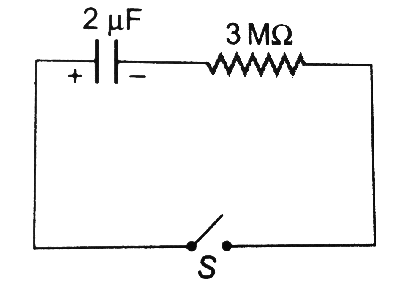 A(0.37)10μCB(0.37)210μCC(0.63)10μCD(0.63)210μC
The two capacitors, shown in the circuit, are initially uncharged and the cell is ideal.The switch S is closed at t = 0.
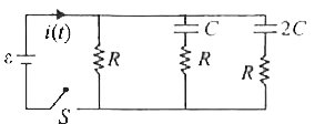
Which of the following functions represents the current i(t), through the cell as a function of time?Here i0,i1,i2 are constants.Ai(t)=i0+i1e−tτ,τ=3C×R3Bi(t)=i0+i1e−tτ+i2e−t2τ,τ=RCCi(t)=i1+i1e−tτ,τ=3C×R3Di(t)=i0+i1e−tτ,τ=3RCConsider a L-R circuit shown in figure. There is no current in circuit switch S is closed at t = 0, time instant when current in inductor is equal to current in resistor 2R will be :
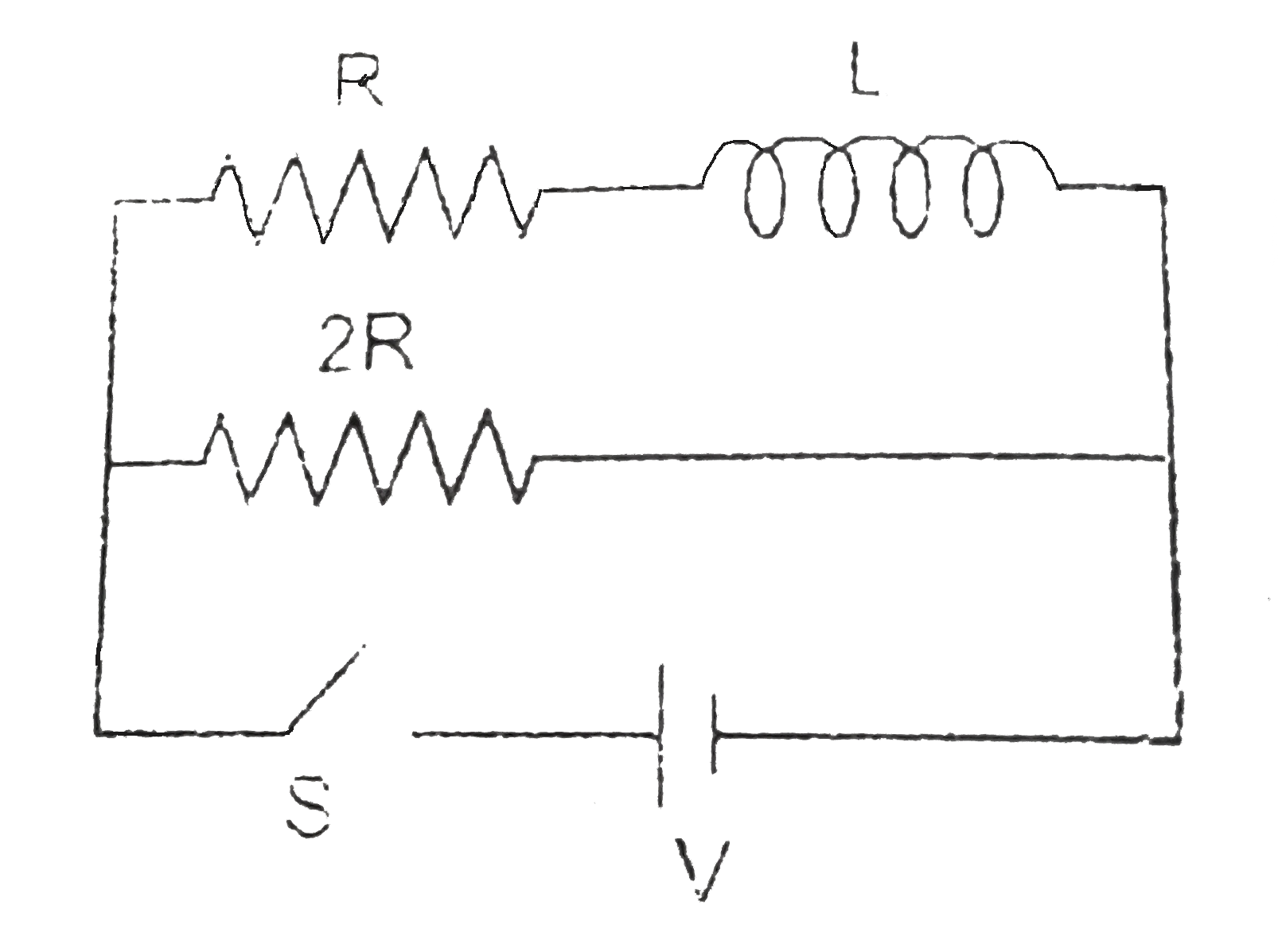 ALRln2B2LRln2CL2Rln2DL2R
Consider a L-R circuit shown in figure. There is no current in circuit switch S is closed at t = 0, time instant when current in inductor is equal to current in resistor 2R will be :

View SolutionPassage-III
In the circuit shown, the battery is ideal with emf V. The capacitor is initially uncharged. The switch is closed at time t = 0
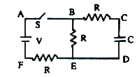
The current in the branch BE at t=∞ is
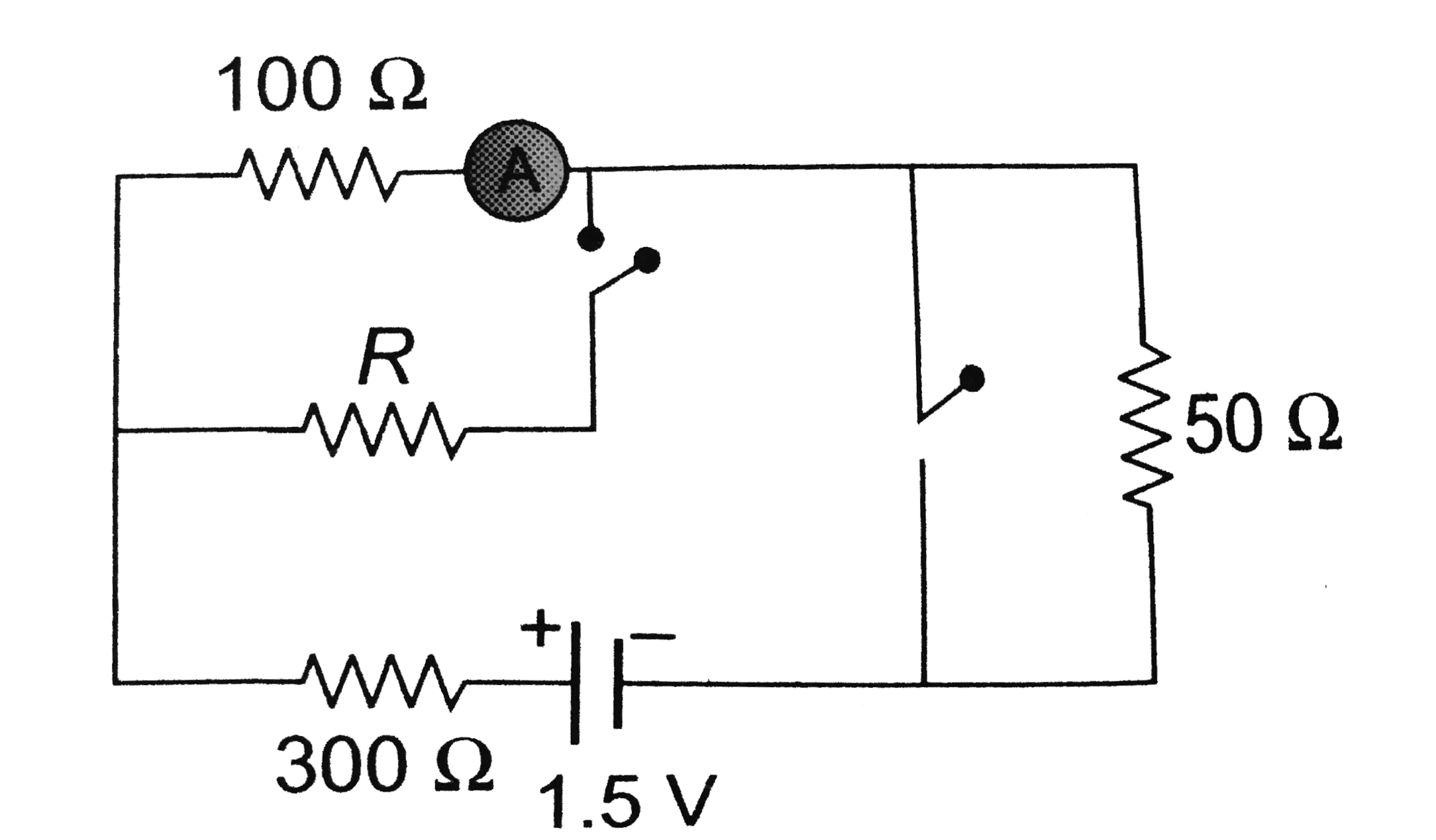
View SolutionIn the circuit shown in figure the reading of ammeter is the same with both switches open as with both closed. Then find the resistance R. (ammeter is ideal).
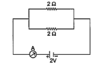
View SolutionIn a circuit shown in figure, the current recorded by an ideal ammeter A is
View SolutionIn the circuit shown in figure the reading of ammeter is the same with both switches open as with both closed. Then find the resistance R. (ammeter is ideal).

View Solution

