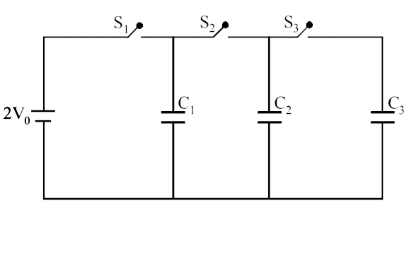
In the circuit shown in the figure, there are two parallel plate capacitors each of capacitance C. The switch S1 is pressed first to fully charge the capacitor C1 and then released. The switch S2 is then pressed to charge the capacitor C2. After some time, S2 is released and then S3 is pressed. After some time
the charge on the upper plate of C1is2CV0
the charge on the upper plate of C1isCV0
the charge on the upper plate of C1is0
the charge on the upper plate of C2is−CV0
After switch S1 is closed, C1 is charged by 2CV0, when switch S2 is closed C1 and C2 both have plate charge CV0. When S3 is closed, then upper plate of C2 becomes charged by −CV0 and lower plate by +CV0
Similar Questions
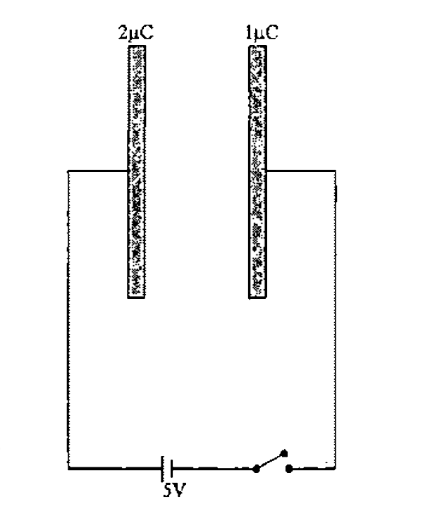
A parallel plate capacitor of capacitance 0.1μF is shown in the figure. Its two plates are given charges 2μC and 1μC. Find the value of heat dissipated after switch is closed :
View SolutionThe time constant, for charging of capacitor C, when switch S is closed as shown in the figure , is
_PHY_E01_020_Q01.png)
View Solution
Knowledge Check
In the circuit shown in the figure, the capacitor C is charged to a potential Vo. The heat generated in the circuit when the switch S is closed, is
ACV20B2CV20C4CV20D8CV20In the circuit shown in figure, the capacitor is charged with a cell of 5V.If the switch is closed at t=0, then at t=12s, charge on the capacitor is
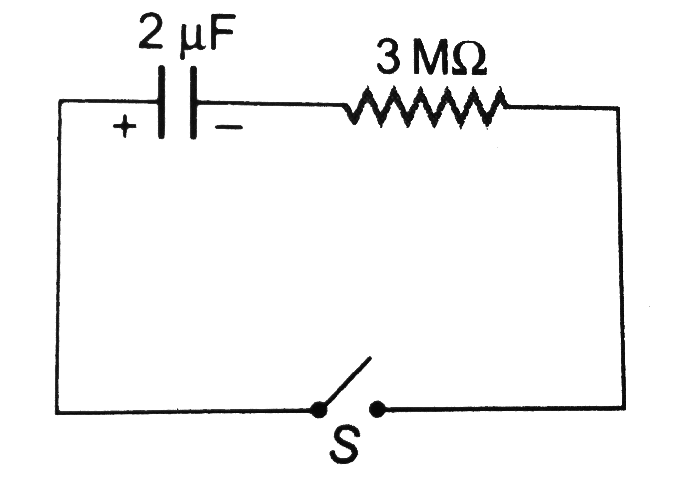 A(0.37)10μCB(0.37)210μCC(0.63)10μCD(0.63)210μC
The charge on each of the capacitors 0.16 ms after the switch S is closed in figure is :
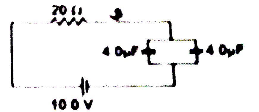 A24μCB26.8μCC25.2μCD40μC
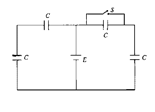
In the circuit shown in figure, each capacitor has a capacitance C and cell voltage is E. If switch S is closed, then calculate the work done by battery after closing the switch.
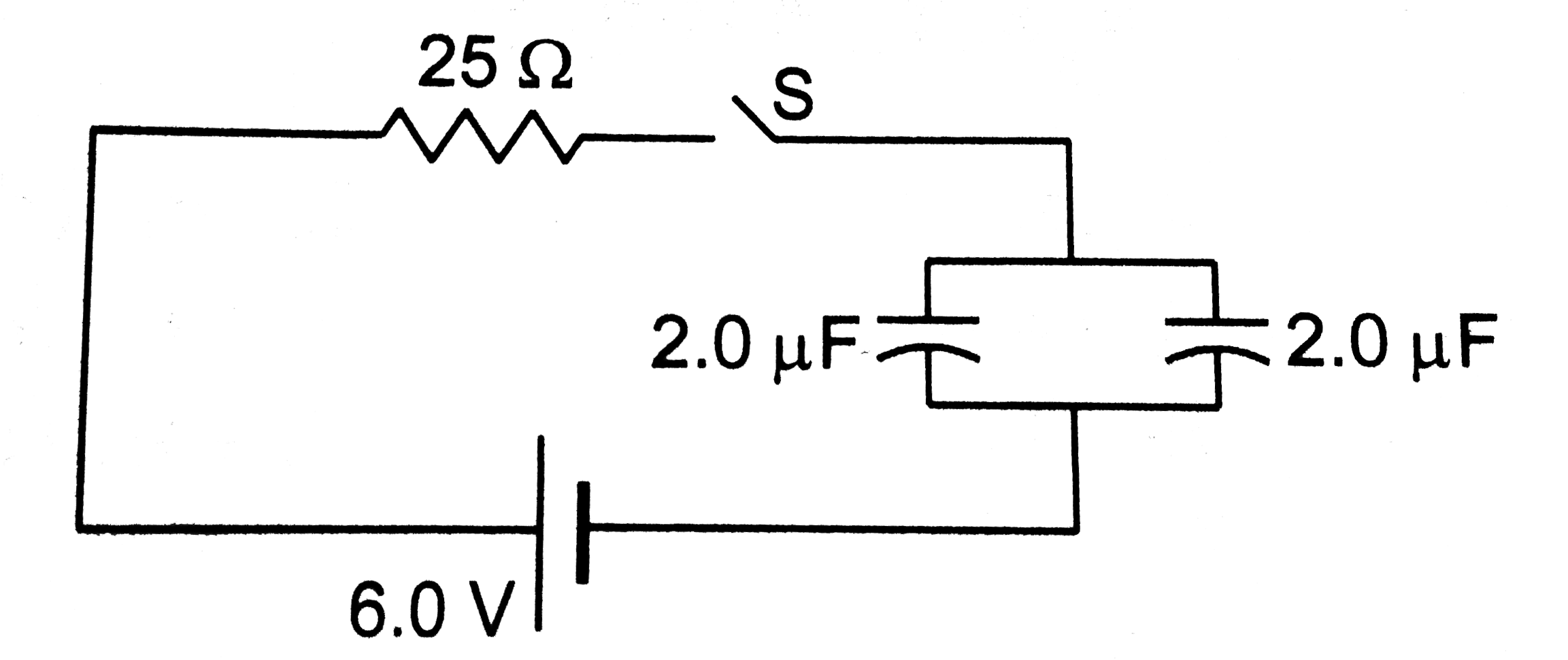
View SolutionFind the charge on each of the capacitor 0.20ms after the switch S is closed in Figure.
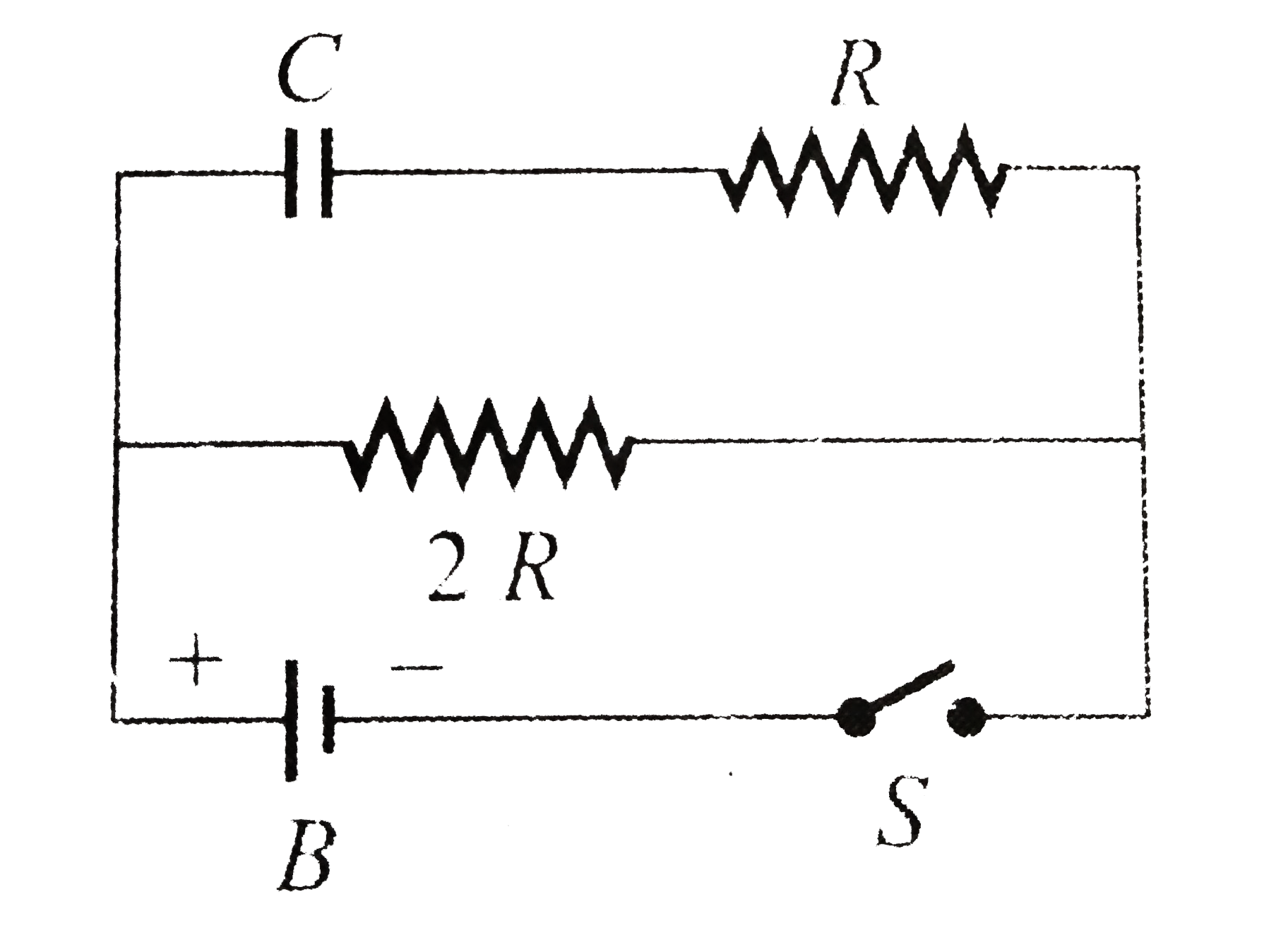
View SolutionIn the circuit shown in fig, if the switch S is closed at t=0 , the capacitor charges with a time constant
View SolutionFind the charge on each of the capacitor 0.20ms after the switch S is closed in Figure.

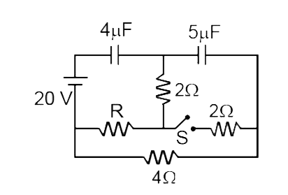
View SolutionFind heat produced in the capacitors after long time on closing the switch S
View Solution
