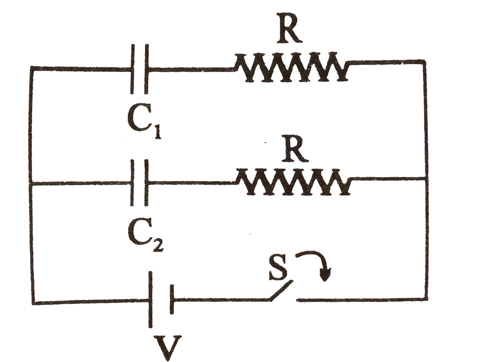
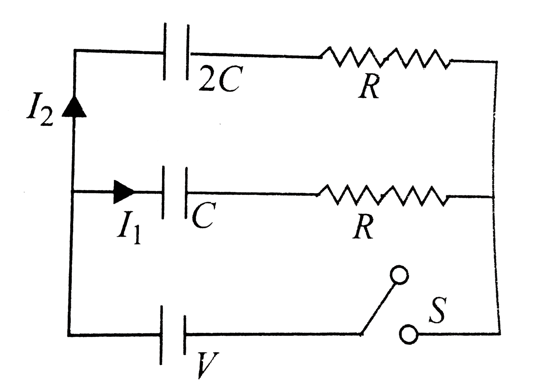
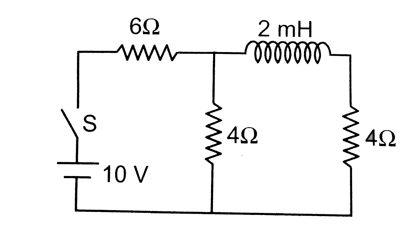
In the circuit shown, switch Sis closed att=O. Let i1andi2be the current at any finite time I, then the ratio i1/i2 is
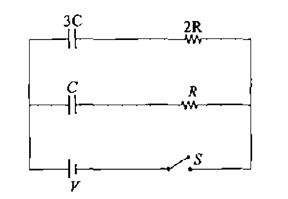
is consant
increases with time
decreases with time
first increases and then decreases
The correct Answer is:B
Step by step video, text & image solution for In the circuit shown, switch Sis closed att=O. Let i_(1) and i_(2) be the current at any finite time I, then the ratio i_(1)//i_(2) is by Physics experts to help you in doubts & scoring excellent marks in Class 11 exams.
Updated on:21/07/2023Topper's Solved these Questions
- ELECTROSTATICSBook:DC PANDEYChapter:ELECTROSTATICSExercise:Comprehension
Explore 36 Videos
- ELECTROSTATICSBook:DC PANDEYChapter:ELECTROSTATICSExercise:Matrix Matching
Explore 2 Videos
- ELECTROSTATICSBook:DC PANDEYChapter:ELECTROSTATICSExercise:Integer
Explore 17 Videos
- ELASTICITYBook:DC PANDEYChapter:ELASTICITYExercise:Medical entrances s gallery
Explore 21 Videos
- EXPERIMENTSBook:DC PANDEYChapter:EXPERIMENTSExercise:Subjective
Explore 15 Videos
Similar Questions
Knowledge Check
In the circuit shown switch S is closed at t=0. Let i1 and i2 be the current at any finite time t then the ratio i1i2
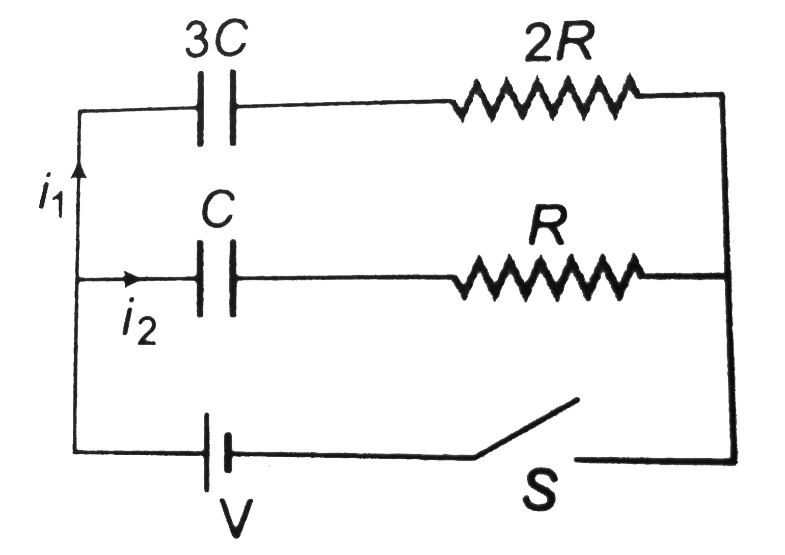 Ais constantBincreases with lineCdecrease with timeDfirst increases then decreases
In the circuit shwon in fig. switch S is closed at time t = 0. Let I1andI2 be the currents at any finite time t, then the ratio I1/I2
 Ais constantBincreases with timeCdecreases with timeDfirst increases, then decreases
In the circuit shown, the switch is closed at t=0, the currents I1,I2 and I3 are
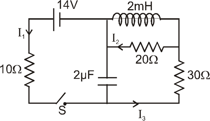 A1.4A,0,0B1.4 A,0.70 A,0.70 AC0,0,0D1.2A,0.6A,0.6A
In the circuit shown in figure switch S is closed at time t=0
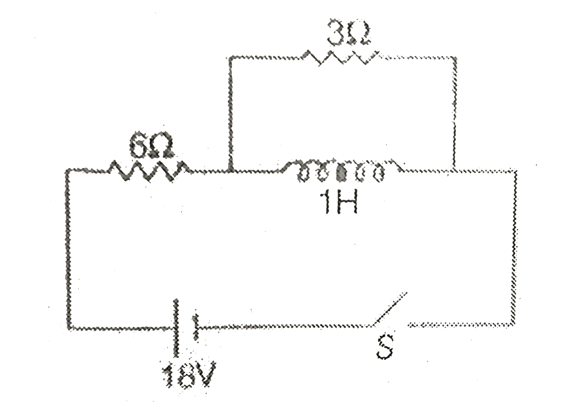
Current I from the battery at time t is given by
View SolutionIn the circuit shown below the switch is closed at t=0. For 0<t<R(C1+C2), the current I1 in the capacitor C1 in terms of total current I is
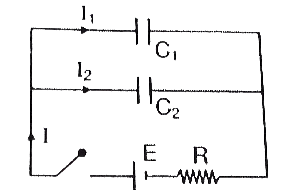
View SolutionIn the given circuit, let i1 be the current drawn battery at time t=0 and i2 be steady current at t=∞ then the ratio i1i2 is
View SolutionIn the circuit shown in the figure The steady state currents i1andi2 in the coils after the switch S is closed are
View SolutionIn the circuit as shown in figure, the ratio of current i1/i2 is
View Solution
