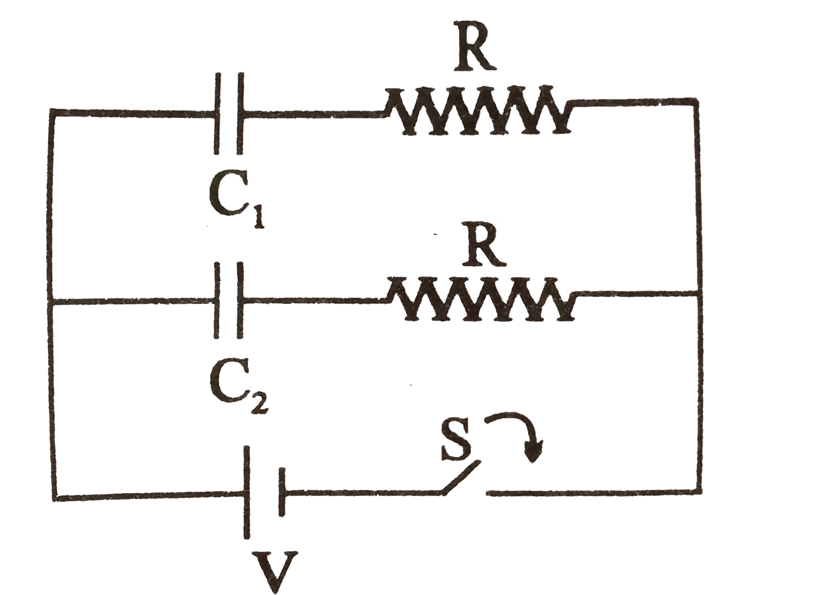
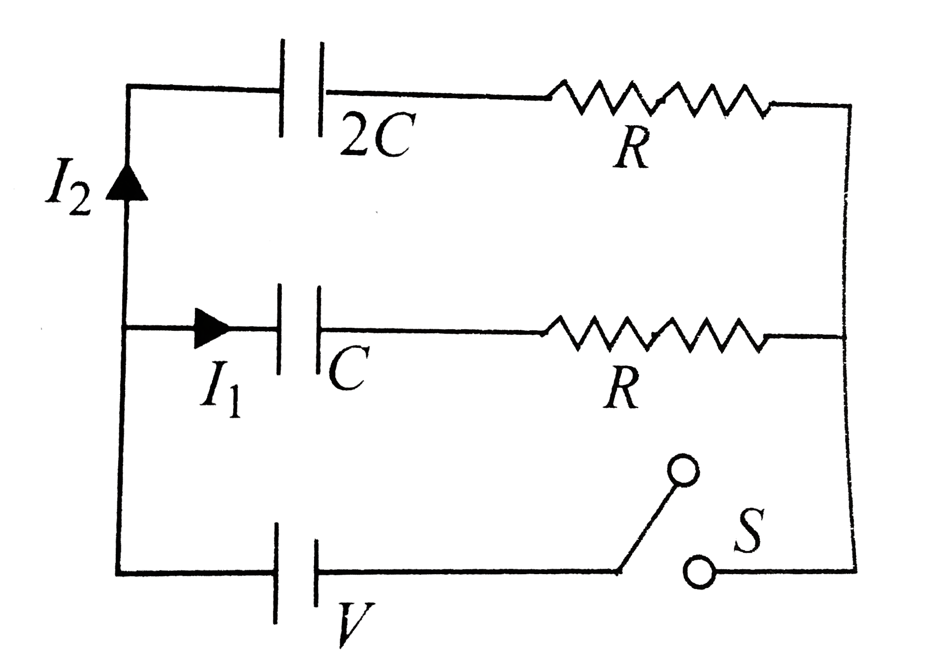
In the ciruit shown in figured C1=2C2. SwitchS is closed at timt t=0.Let i1 and i2 be currents flowing through C1 and C2 at any time t, then the ratioi1/i2
is constant
increases with increases in time t
decreases with increase in time t
first increases then decreases
The correct Answer is:B
i1=VRetRC1&i2=VRetRC2
i1i2=e−t/RC1e−t/RC2⇒i1i2=etRC2−tRC1
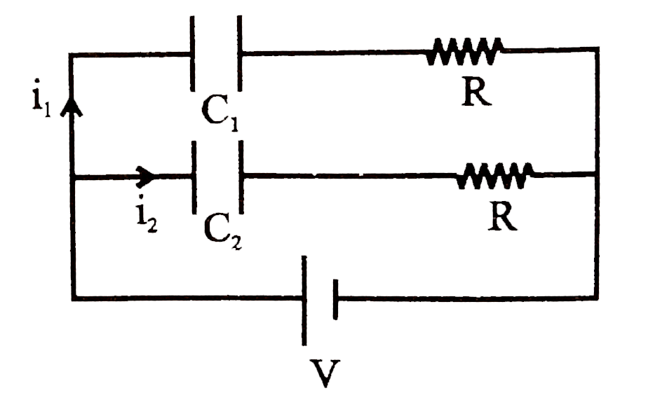
Putting C1=2C2⇒i1i2=et2RC2
Similar Questions
Knowledge Check
In the circuit shwon in fig. switch S is closed at time t = 0. Let I1andI2 be the currents at any finite time t, then the ratio I1/I2
 Ais constantBincreases with timeCdecreases with timeDfirst increases, then decreases
In the circuit shown in figure switch S is closed at time t=0
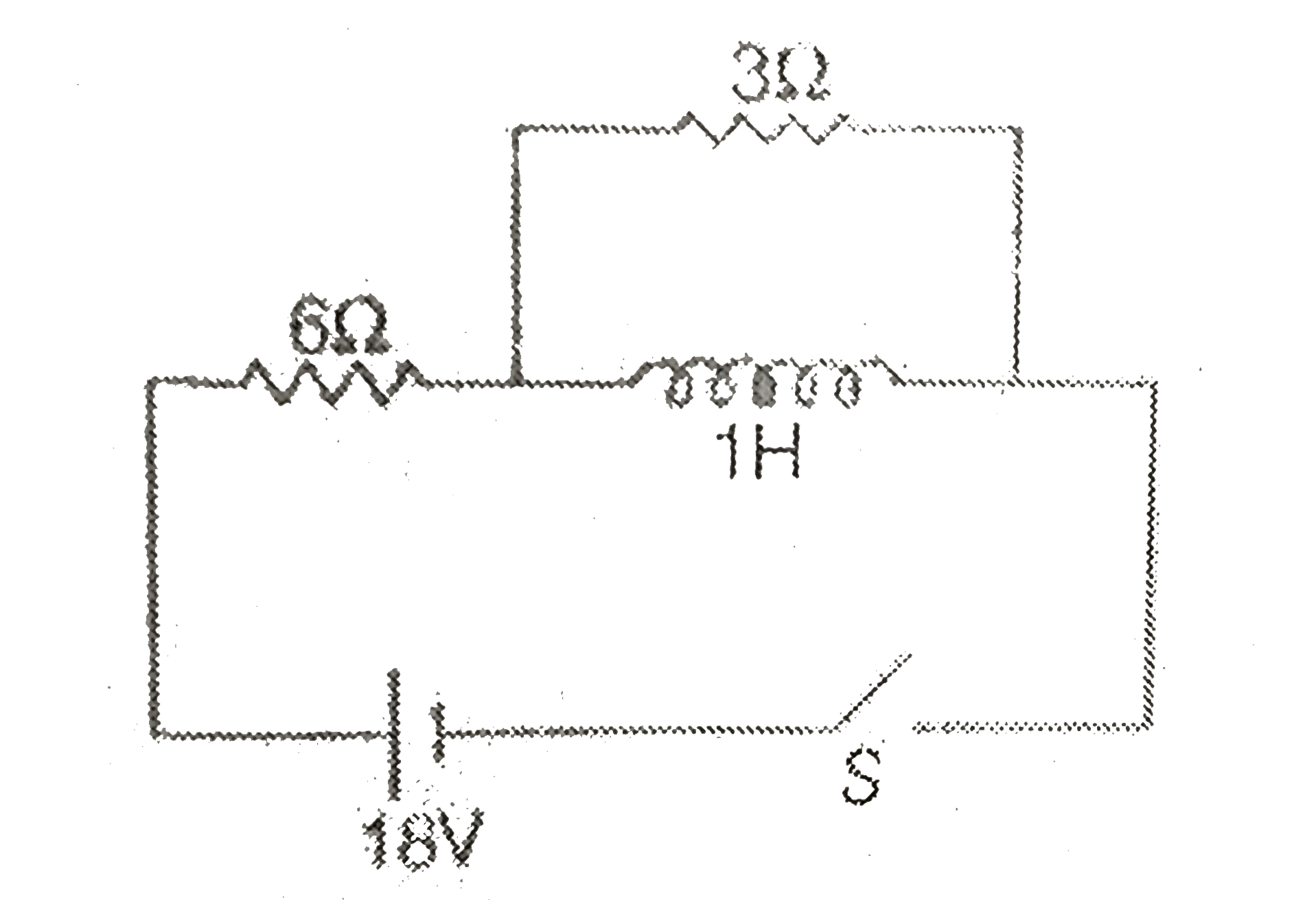
Current I from the battery at time t is given byA3(1−e−2t)B3+e−2t)C3(1-e^(-t/9))D3−e−2tIn the circuit shown, switch Sis closed att=O. Let i1andi2be the current at any finite time I, then the ratio i1/i2 is
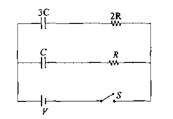 AConstantBIncreases with timeCDecreases with timeDFirst increases and then decreases
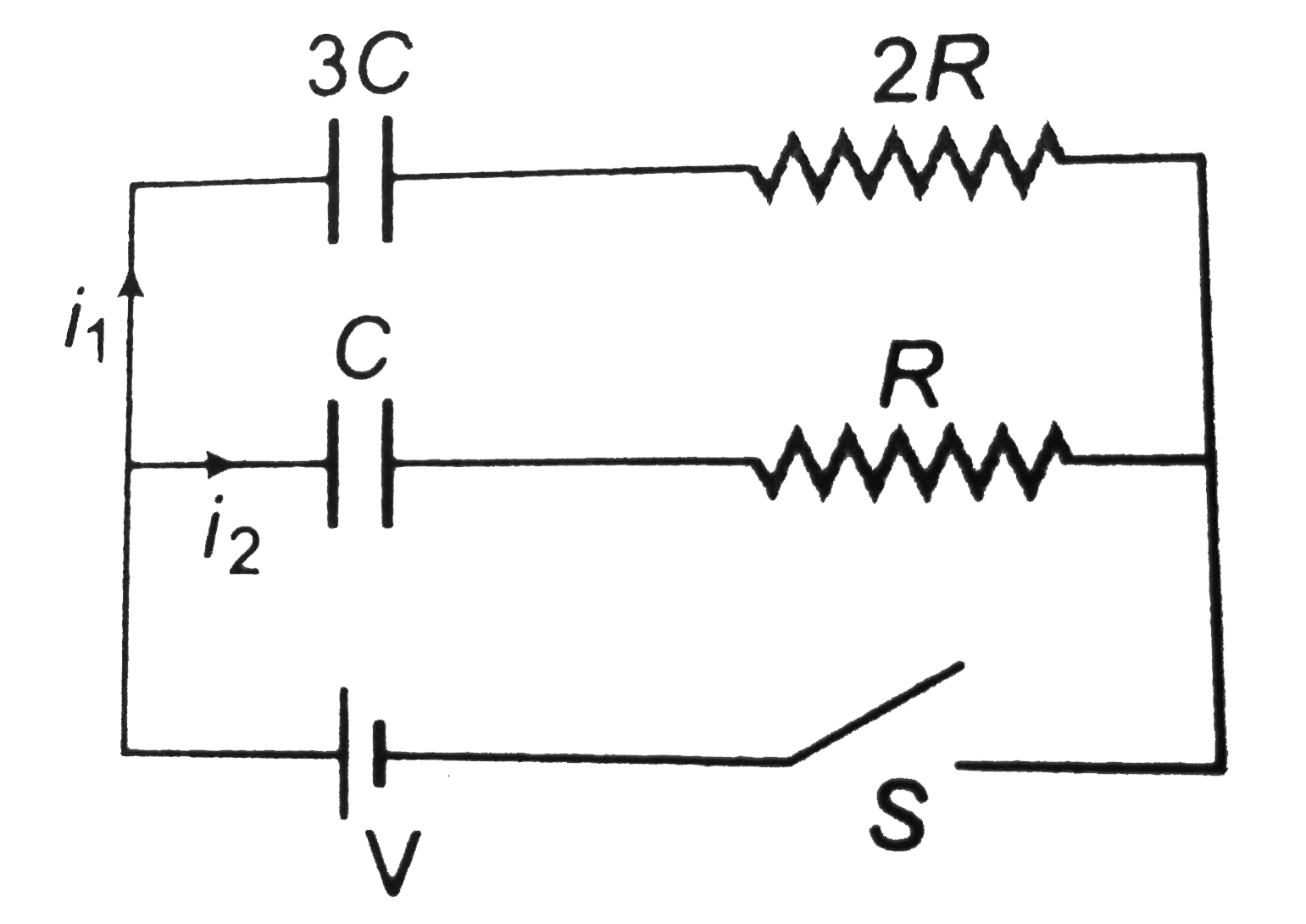
In the circuit shown switch S is closed at t=0. Let i1 and i2 be the current at any finite time t then the ratio i1i2
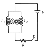
View SolutionIn the figure shown in key is switched on a t = 0. Let I1 and I2 be the current through inductors having self inductances L1 and L2 at any time t respectively. The magnetic energy stored in the inductors 1 and 2 be U1 and U2. Then U1/U2 at any instant of time is
View SolutionIn the circuit shown in figure C1=2C2. Capacitance C1 is charged to a potential of V. The current in the circuit just after the switch S is closed is

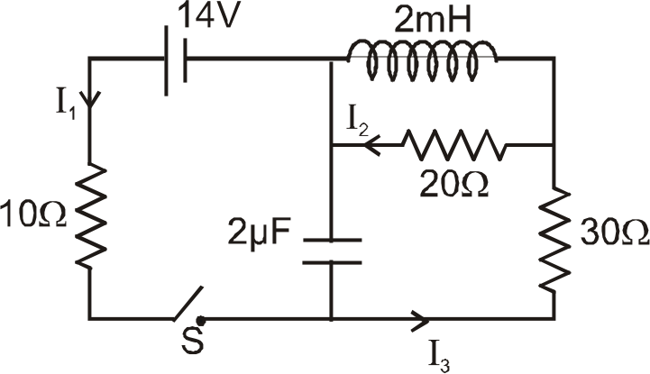
View SolutionIn the circuit shown, the switch is closed at t=0, the currents I1,I2 and I3 are
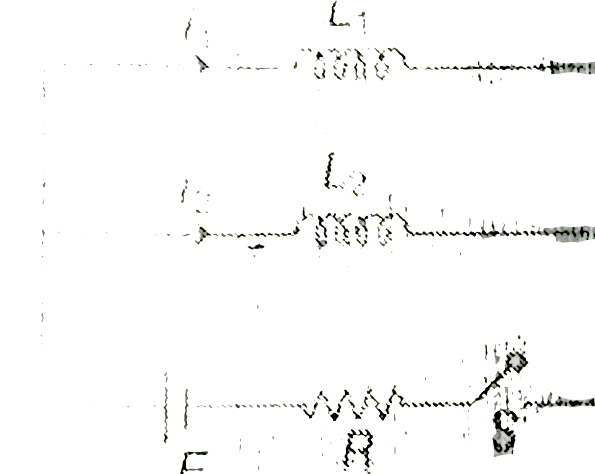
View SolutionIn the circuit shown in the figure The steady state currents i1andi2 in the coils after the switch S is closed are
View Solution

