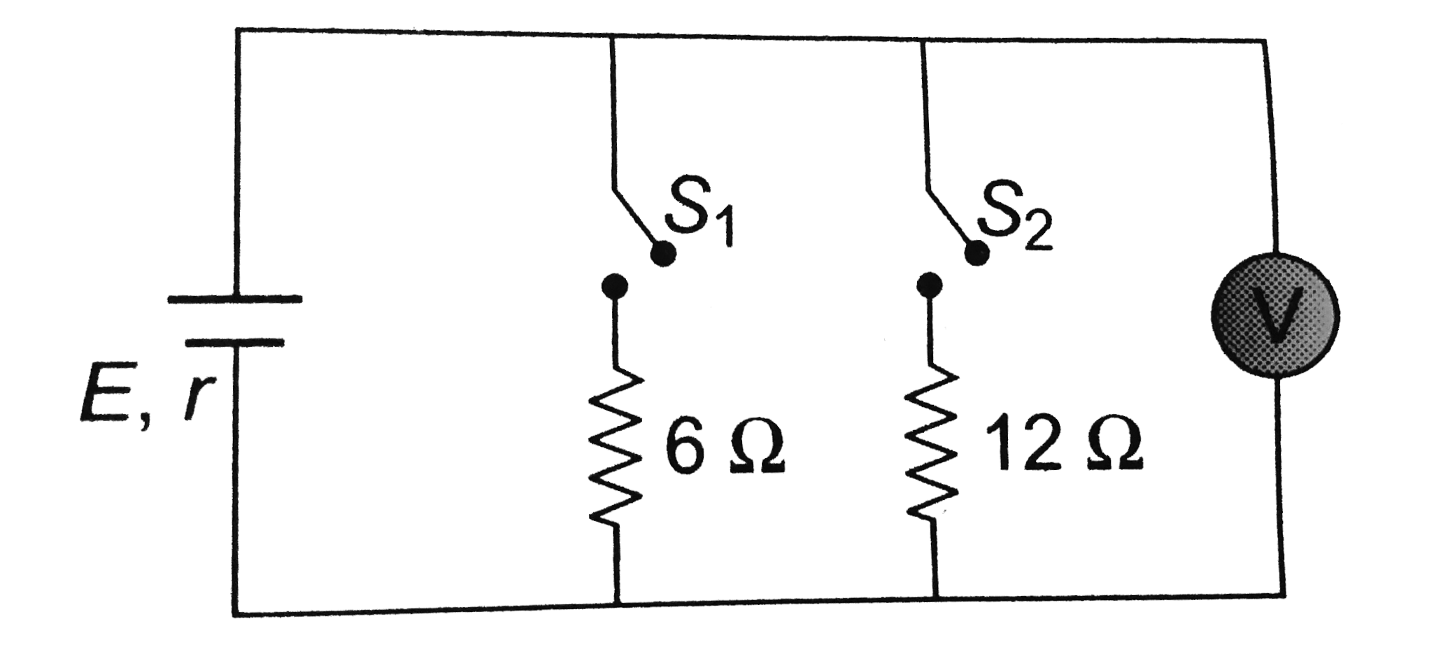
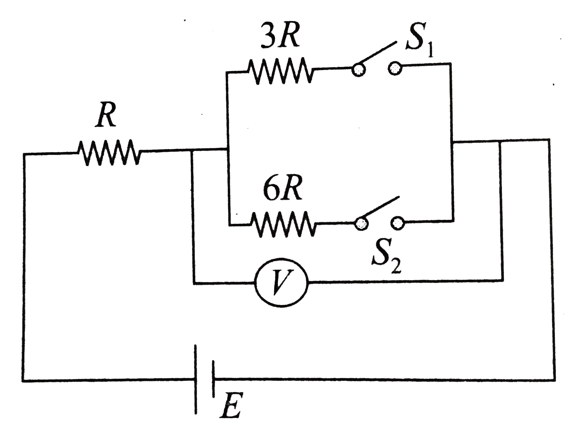
In the circuit shown, when switch S1 is closed and S2 is open, the ideal voltmeter shows a reaiding of 18V. When switch S2 is closed and S1 is open, the reading of voltmeter is 24V. When S1 and S2 both are closed, the voltmeter reading will be
14.4V
20.6V
24.4V
10.8V
The correct Answer is:A
(a) Terminal potential difference across the terminals of cell E
V=E−ir=E−(Er+R)r=ERR+r
According to question
18=6E6+r
and 24=12E12+r
Solving (i) and (ii), we get r=6Ω,E=36V
When both S1 and S2 are closed, the effective external resistance in the circuit will be.
R=6×1218=4Ω
So, V=ERr+R=36×46+4=14410=144 volt
V=14.4 volt
Thus, choice (a) is correct.
Topper's Solved these Questions
- CURRENT ELECTRICITYBook:A2ZChapter:CURRENT ELECTRICITYExercise:Section - A
Explore 1 Video
- CURRENT ELECTRICITYBook:A2ZChapter:CURRENT ELECTRICITYExercise:Section B - Assertion Reasoning
Explore 28 Videos
- CURRENT ELECTRICITYBook:A2ZChapter:CURRENT ELECTRICITYExercise:Heating Effect Of Current
Explore 40 Videos
- ATOMIC PHYSICSBook:A2ZChapter:ATOMIC PHYSICSExercise:Section D - Chapter End Test
Explore 30 Videos
- DUAL NATURE OF RADIATION AND MATTERBook:A2ZChapter:DUAL NATURE OF RADIATION AND MATTERExercise:Section D - Chapter End Test
Explore 30 Videos
Similar Questions
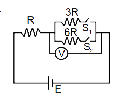
In the circuit shown in figure reading of voltmeter is V1 when only S1 is closed , reading of voltmeter is V2 when only S2 is closed . The reading of voltmeter is V3 when both S1 and S2 are closed then
View SolutionIn the circult shown
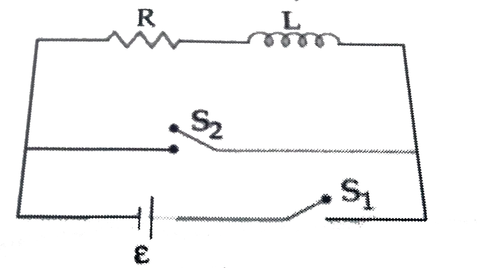 the switch S1 is closed at time t=0 and the swith S2 is kept open. At some later time (t0) ,the swith S1 is opened and S2 is closed .The behaviour of the current I as a function of time 't' is given by :
View Solution
Knowledge Check
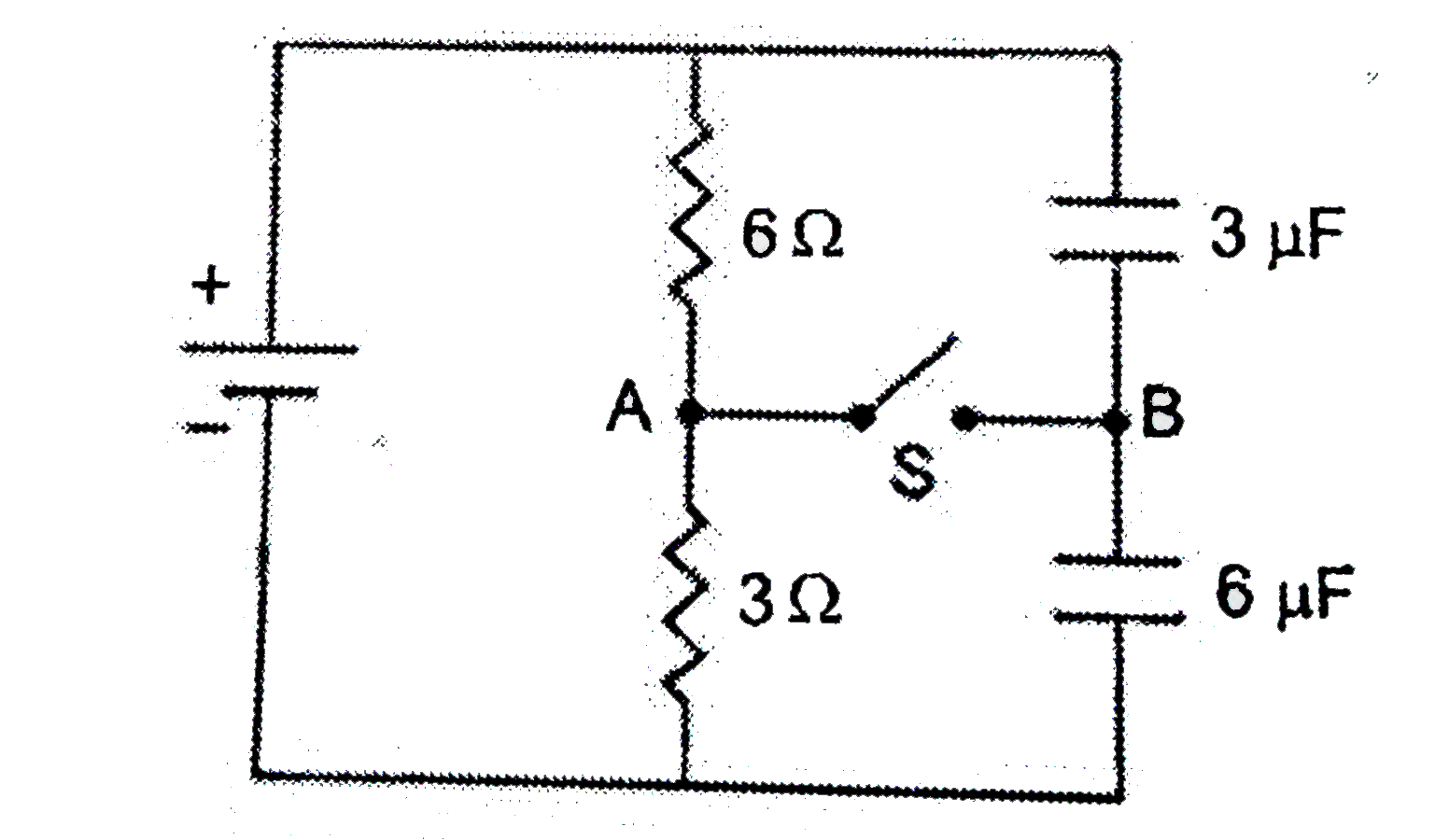
In the circuit shown above, when then switch S is closed,Ano charge flows through SBcharge flows from A to BCcharge flows from B to ADcharge flows initially from A to B and later from B to AIn the circuit shown in figure, switch S is initially closed and S is open. Find V-V
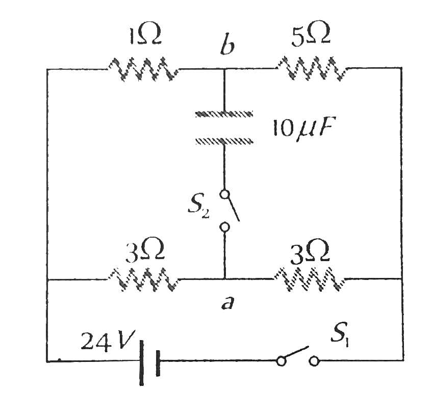 A4VB8VC12VD16V
After switch S2 is closed and S1 is opened, the maximum value of current through the inductor is:
A(√CL)EB(√C2L)EC(√3C2L)ED(√5C4L)E
Consider the circuit shown in figure . With switch S1 closed and the other two switches open, the circuit has a time constant 0.05sec. With switch S2 closed and the other two switches open, the circuit has a time constant 2 sec. With switch S3 closed and the other two switches open, the circuit oscillates with a period T. Find T ( in sec ) . ( Take π2=10)

View SolutionAt any time S1 switch is opened and S2 is closed then find out heat generated in circuit.
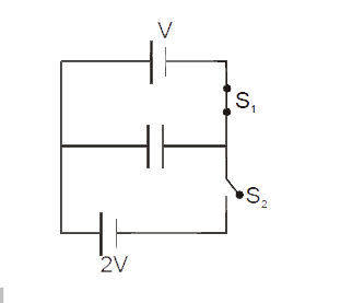
View SolutionIn the circuit shown in figure, reading of voltmeter is V1 when only S1 is closed, reading of voltmeter is V2 when only S2 is closed, and reading of voltmeter is V3 when both S1andS2 are closed. Then .
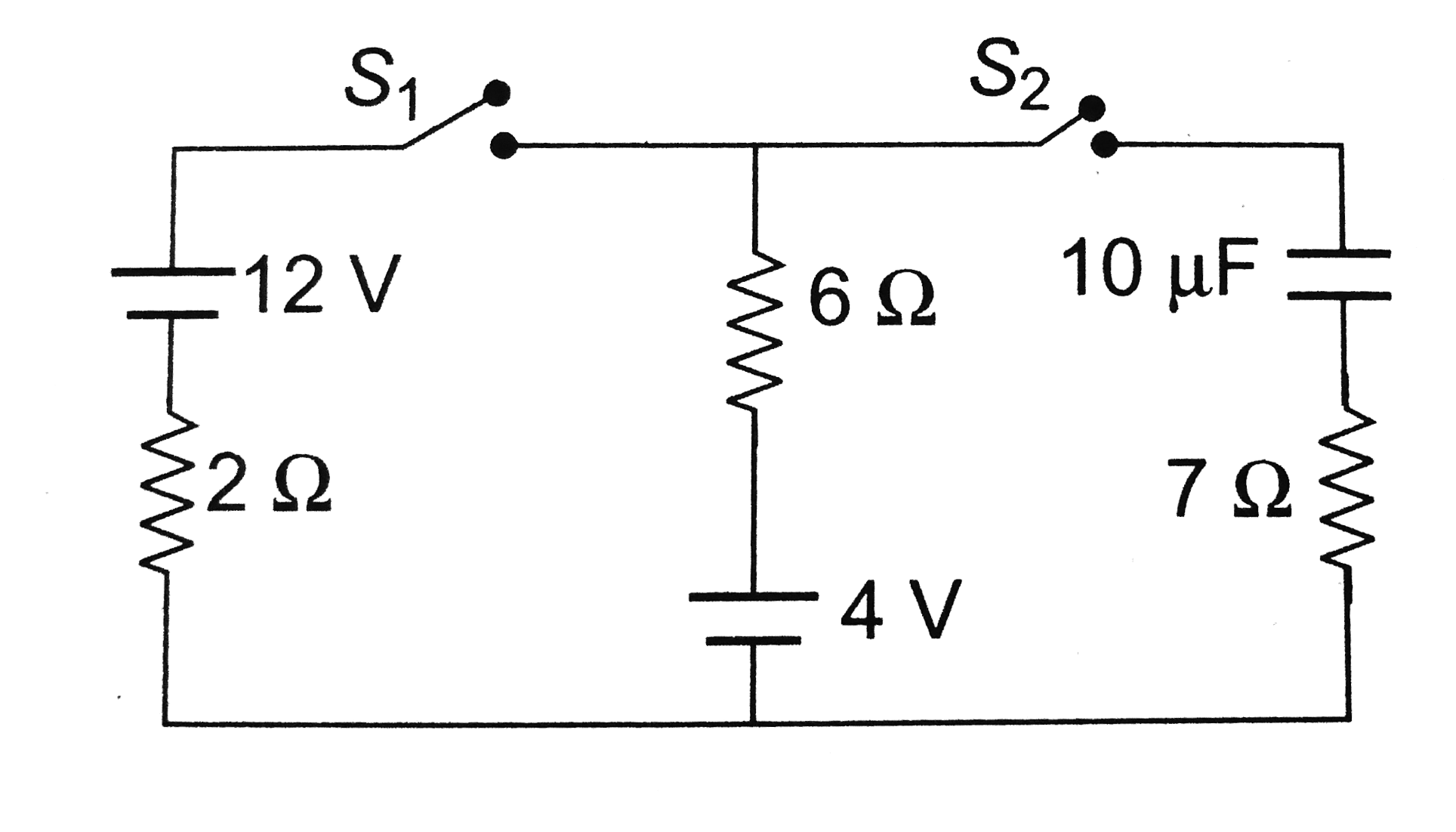
View SolutionIn the circuit shown in the figure, if switches S1 and S2 have been closed for a long time, then charge on the capacitor.
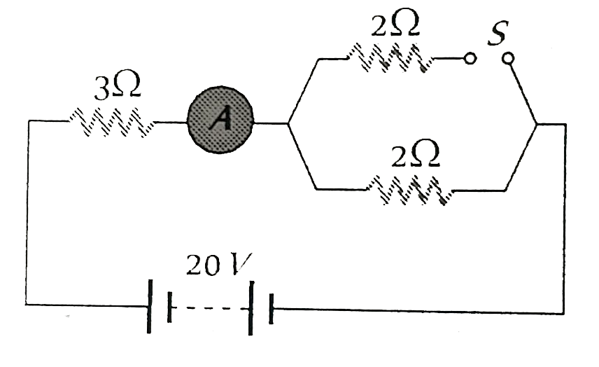
View SolutionIn the circuit shown, the reading of ammeter when switch S is open and when switch S is closed respectively are
View Solution