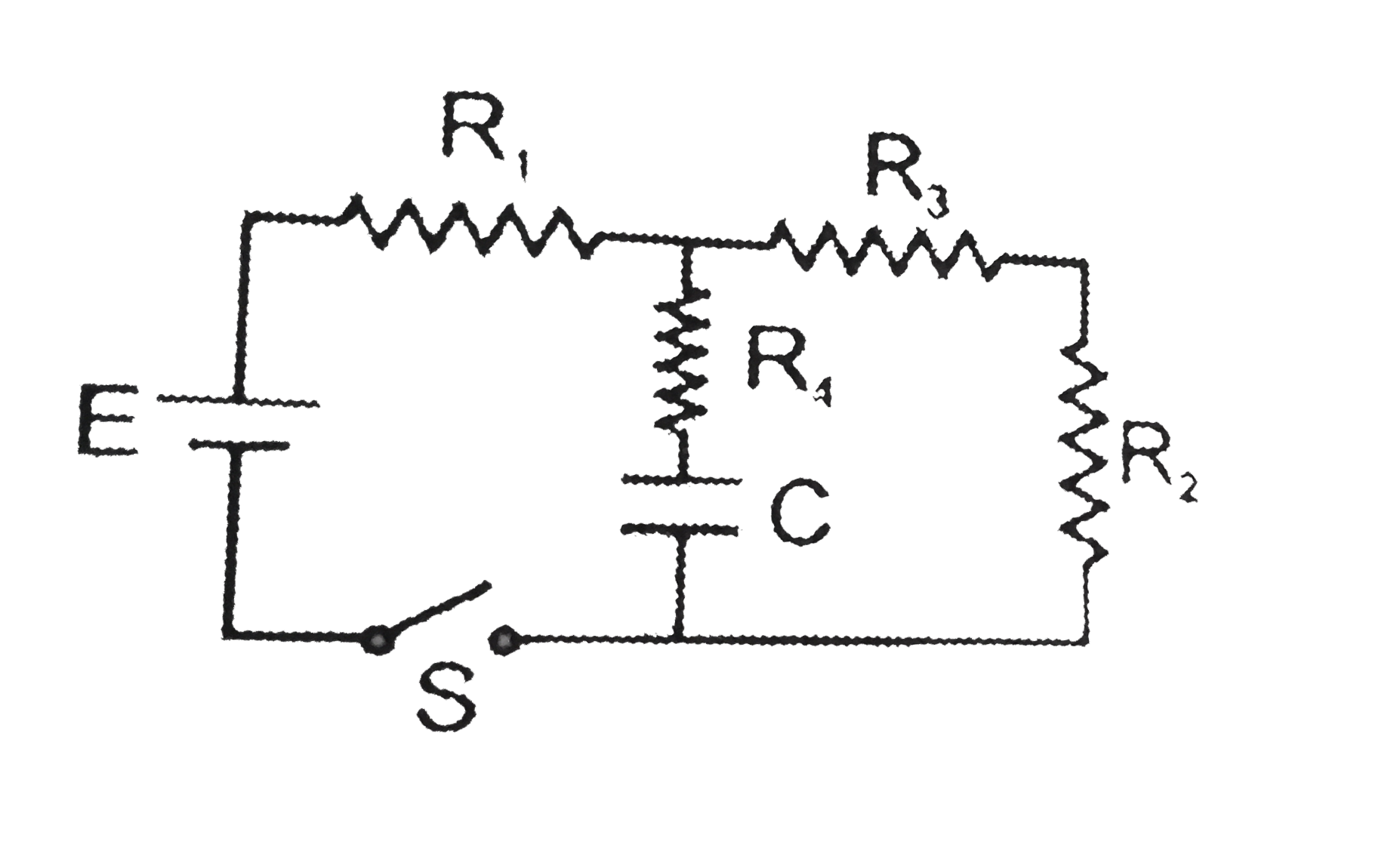
In the circuit shows in Fig the switch is closed at .

At
At any time
At any time t,
At and are independent of and
The correct Answer is:A, B
The coils are in parallel, so
Initially ,
So
Topper's Solved these Questions
- INDUCTANCEBOOK - CENGAGE PHYSICSCHAPTER - INDUCTANCEEXERCISE - Exercises (assertion-reasoning)
2 Videos
- INDUCTANCEBOOK - CENGAGE PHYSICSCHAPTER - INDUCTANCEEXERCISE - Exercises (linked Compreshension)
36 Videos
- INDUCTANCEBOOK - CENGAGE PHYSICSCHAPTER - INDUCTANCEEXERCISE - Exercises (single Correct )
65 Videos
- HEATING EFFECT OF CURRENTBOOK - CENGAGE PHYSICSCHAPTER - HEATING EFFECT OF CURRENTEXERCISE - Thermal Power in Resistance Connected in Circuit
28 Videos
- KINETIC THEORYBOOK - CENGAGE PHYSICSCHAPTER - KINETIC THEORYEXERCISE - Question Bank
31 Videos
Similar Questions
In the circuit shown in figure the switch S is closed at t = 0. A long time after closing the switch
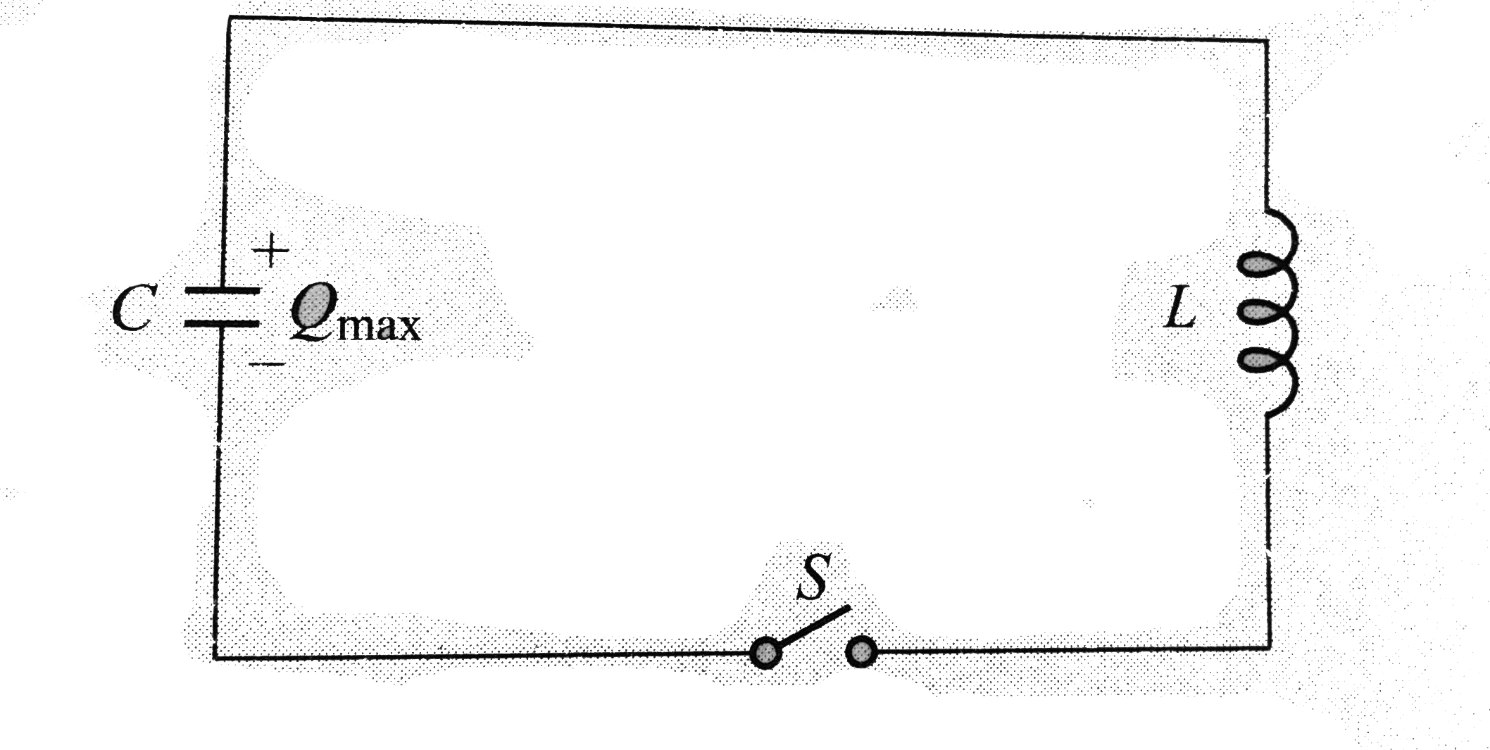
View SolutionIn an LC circuit as shows in Fig. the switch is closed at t=0.Qmax=100μC, L=40mH, C=100μF.
a. Determine the equation for instantaneous change on the capacitor.
b. Determine the equation for instantaneous current in the circuit.
View Solution
Knowledge Check
In the circuit as shown in figure the switch is closed at t=0.
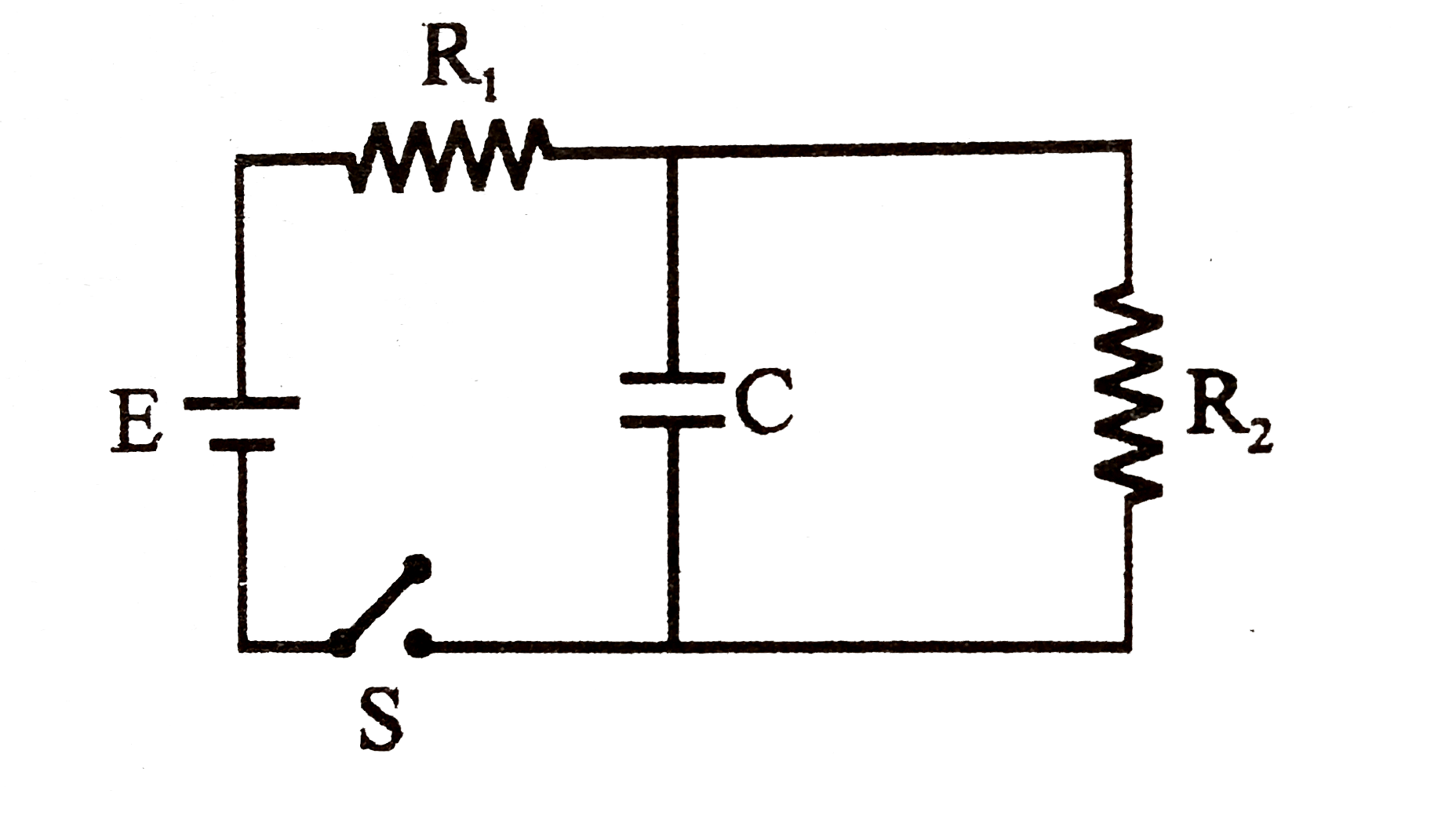
At the instant of closing the switchAthe battery delivers maximum currentBno current flows through CCvoltage drop across R2 is zeroDthe current through the battery decreases with time finally becomes zeroIn the circuit shown in fig, if the switch S is closed at t=0 , the capacitor charges with a time constant
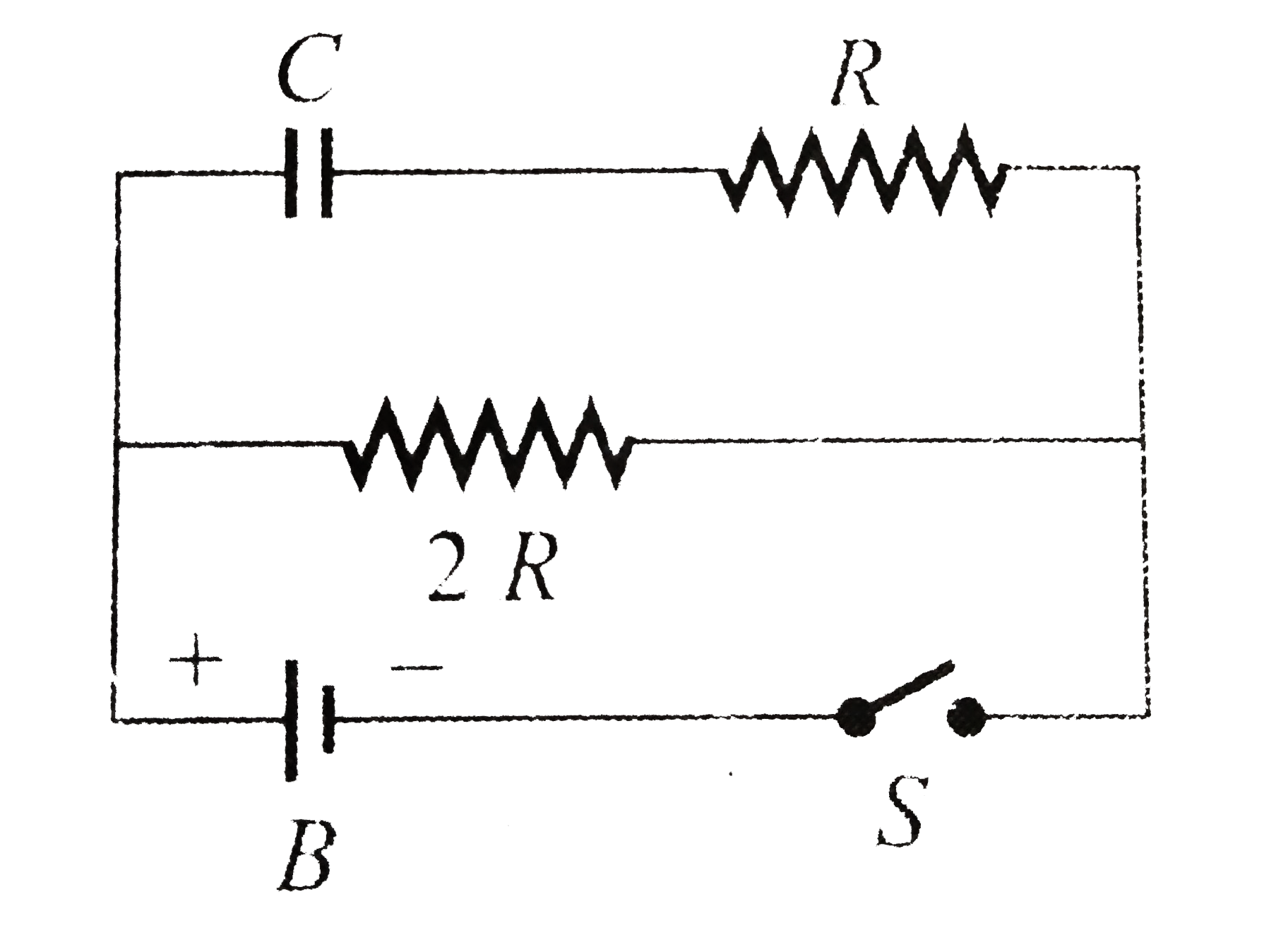 ARCB3RCC23RCDRCIn(23)
In the circuit as shown in figure the switch is closed at t=0.
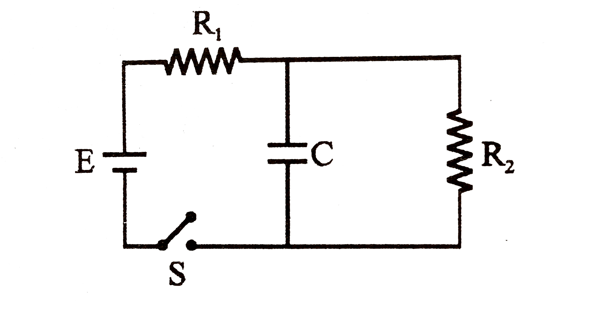
A long time after closing the switchAvoltage drop across the capacitor is EBcurent through the battery is E/R1+R2Cenegru stores in the capacitor is
12C(R2ER1+R2)2Dcurrent through the capacitor becomes zero
In an LC circuit as shows in Fig. the switch is closed at t=0.Qmax=100μC, L=40mH, C=100μF.
a. Determine the equation for instantaneous change on the capacitor.
b. Determine the equation for instantaneous current in the circuit.

View SolutionIn the circuit shown in fig, if the switch S is closed at t=0 , the capacitor charges with a time constant

View SolutionConsider the circuit shown in fig. If the switch is closed at t =0, then calculate the values of I,I1 and I2 at a. t =0 , b. =∞
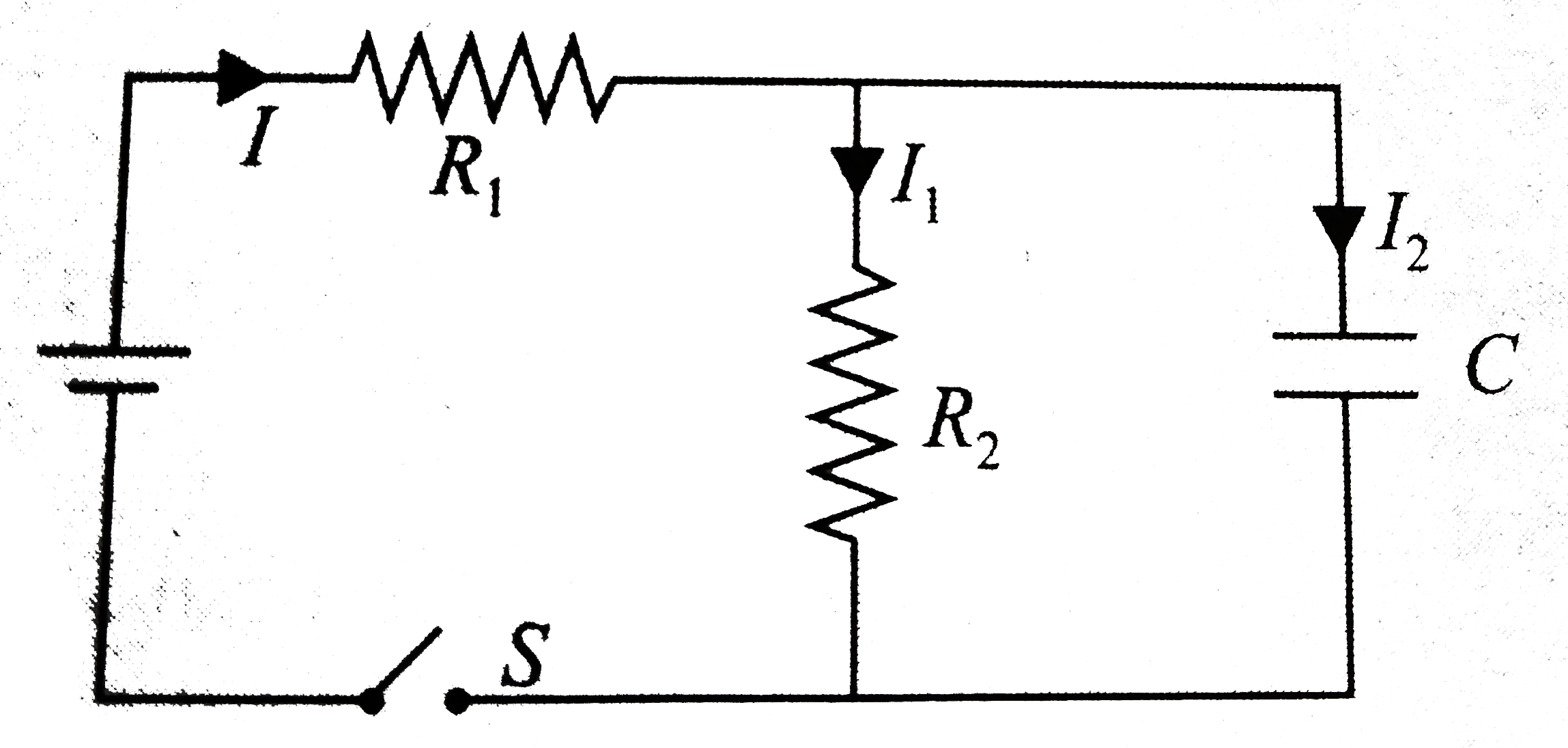
View SolutionConsider the circuit shown in fig. If the switch is closed at t =0, then calculate the values of I,I1 and I2 at a. t =0 , b. =∞

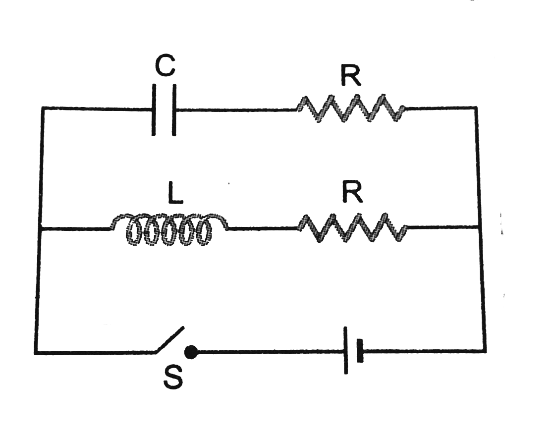
View SolutionIn the circuit shown if Fig. the switch S is closed at time t = 0. The current through the capacitor and inductor will be equal at time t equal (given R=√L/C
View Solution
