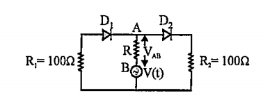
In the curcuit given below D1 and D2 are two identicall diodes and V is a sinusoidal voltage source the voltage drop across the resistance RL

is half rectified
is fully rectified
has same value of peak voltage for positive and negative half cycles
has different value of peak voltage for positive and negative half cycles
In the positive half cycle of the sinusodal voltage diode D1 is forward biased and D2 is reverse biased so the direction fo current through R is opposite for is not rectified Also R1 and are diffierent so the input are different.
Topper's Solved these Questions
- SEMICONDUCTOR ELECTRONICS METERIALS DEVICES AND SIMPLE CIRCUITS BOOK - MODERN PUBLICATIONCHAPTER - SEMICONDUCTOR ELECTRONICS METERIALS DEVICES AND SIMPLE CIRCUITS EXERCISE - COMPETION FILE (JEE(MAIN) & OTHER STATE BOARDS FOR ENGINEERING ENTRANCE )
31 Videos
- SEMICONDUCTOR ELECTRONICS METERIALS DEVICES AND SIMPLE CIRCUITS BOOK - MODERN PUBLICATIONCHAPTER - SEMICONDUCTOR ELECTRONICS METERIALS DEVICES AND SIMPLE CIRCUITS EXERCISE - COMPETION FILE( MULTIPLE CHOICE QUESTIONS )
17 Videos
- SEMICONDUCTOR ELECTRONICS METERIALS DEVICES AND SIMPLE CIRCUITS BOOK - MODERN PUBLICATIONCHAPTER - SEMICONDUCTOR ELECTRONICS METERIALS DEVICES AND SIMPLE CIRCUITS EXERCISE - REVISION EXERCISES (NUMERICAL PROBLEMS )
15 Videos
- RAY OPTICS AND OPTICAL INSTRUMENTSBOOK - MODERN PUBLICATIONCHAPTER - RAY OPTICS AND OPTICAL INSTRUMENTSEXERCISE - CHAPTER PRACTICE TEST
14 Videos
- WAVE OPTICALBOOK - MODERN PUBLICATIONCHAPTER - WAVE OPTICALEXERCISE - CHAPTER PRACTICE TEST
7 Videos
Similar Questions
Knowledge Check
In the circuit given below, V(t) is the sinusoidal voltage source, voltage drop VAB(t) across the resistance R is
 Ais half wave rectifiedBis full wave rectifiedChas the same peak value in the positive and negative half cyclesDhas different peak values during positive and negative half cycle
In the circuit given below, V(t) is the sinusoidal voltage source, voltage drop VAB(t) across the resistance R is
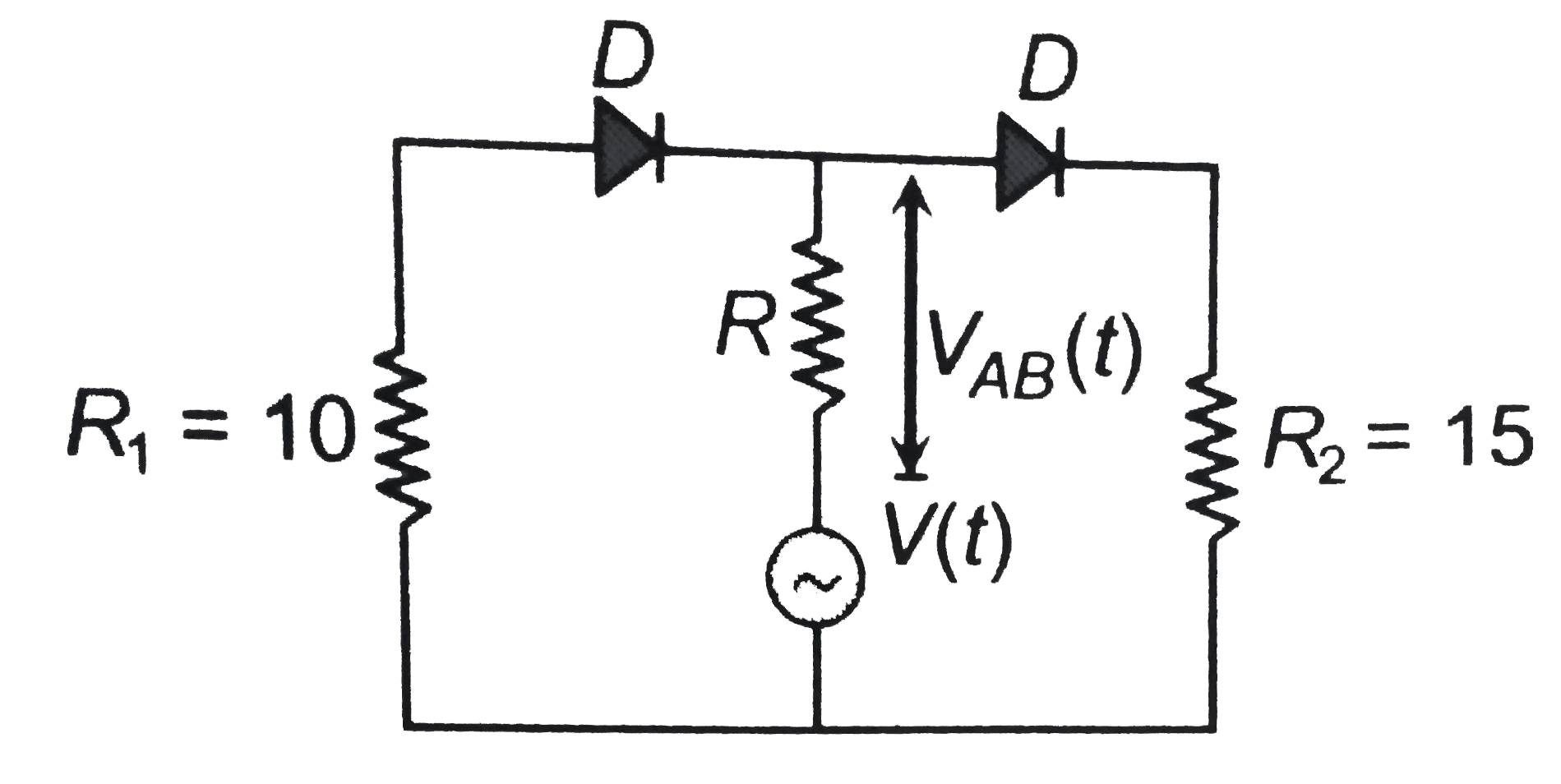 AIs half wave rectifiedBIs full wave rectifiedCHas the same peak value in the positive and negative half cyclesDHas different peak values during positive and negative half cycle
In circuit show below, the resistances are given in ohms and the battery is assumed ideal with emf equal to 3 V. The voltage across the resistance R4 is :
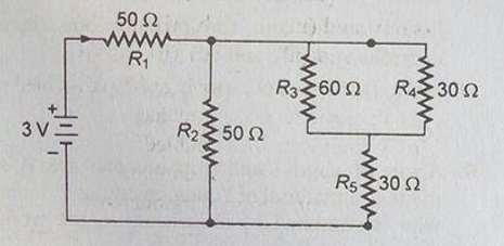 A0.4 VB0.6 VC1.2 VD1.5 V
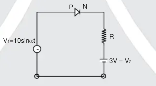
In given circuit, correct curve depicting voltage across resistance R, with time is?
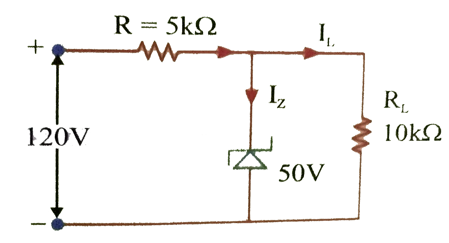
View SolutionFor the circuit shown in figure, Find
(1) the output voltage ,
(2) the voltage drop across series resistance ,
(3) the current through Zener diode.
 .
.
View SolutionIn circuit show below, the resistances are given in ohms and the battery is assumed ideal with emf equal to 3 V. The voltage across the resistance R4 is :

View SolutionA resistance R1 is connected to a source of constant voltage . On connecting a resistance R2 in series with R1
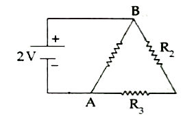
View SolutionIn the electrical circuit (ABC) as shown in the figure given below , the resistances R1,R2andR3 are same and equal to 30 . If a sour ce of voltage 2 V is connected across one arm, the current drawn from the voltage source is
View Solution

