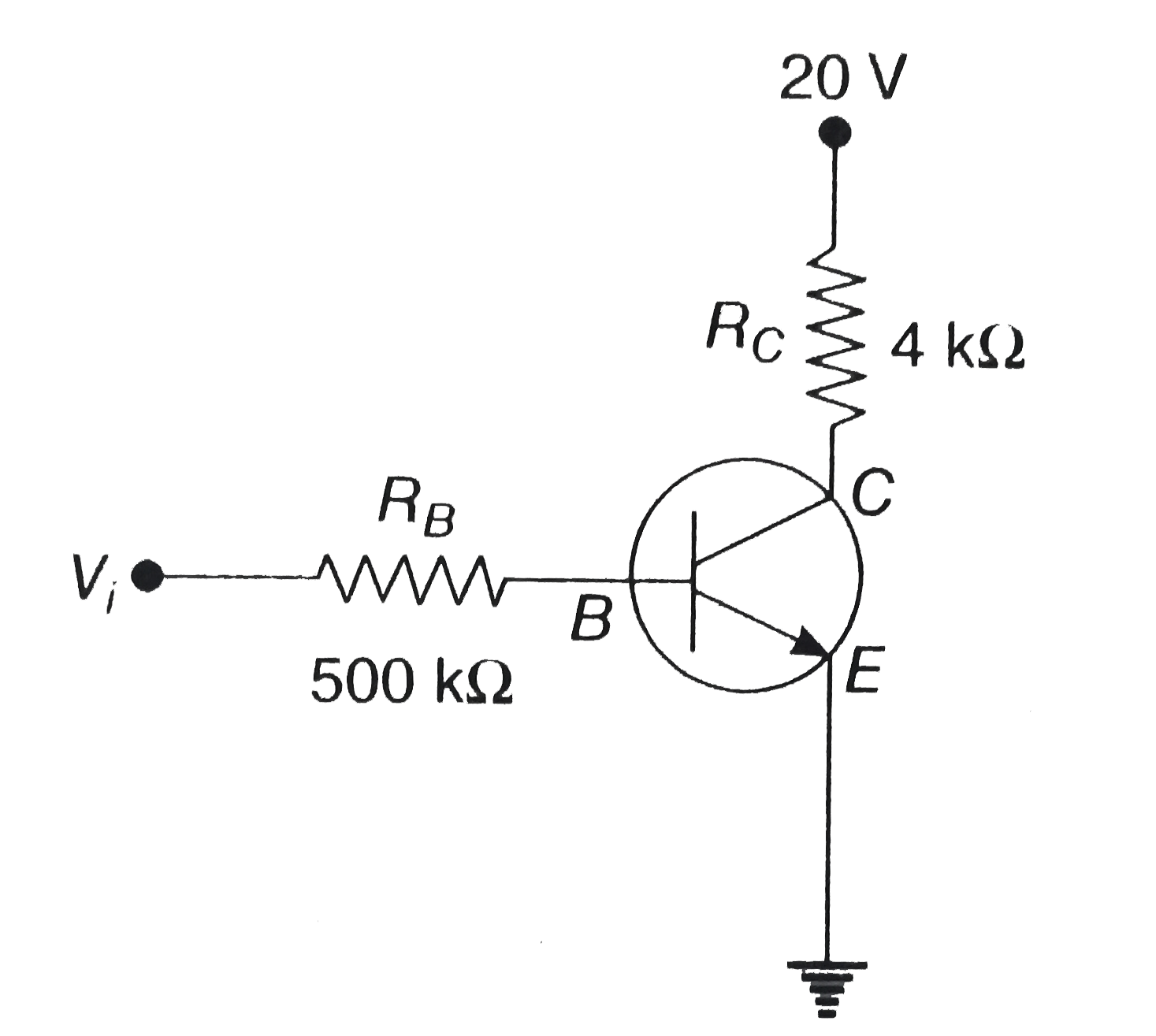
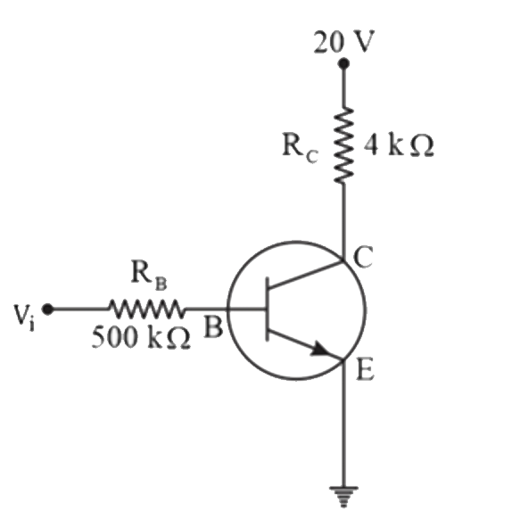
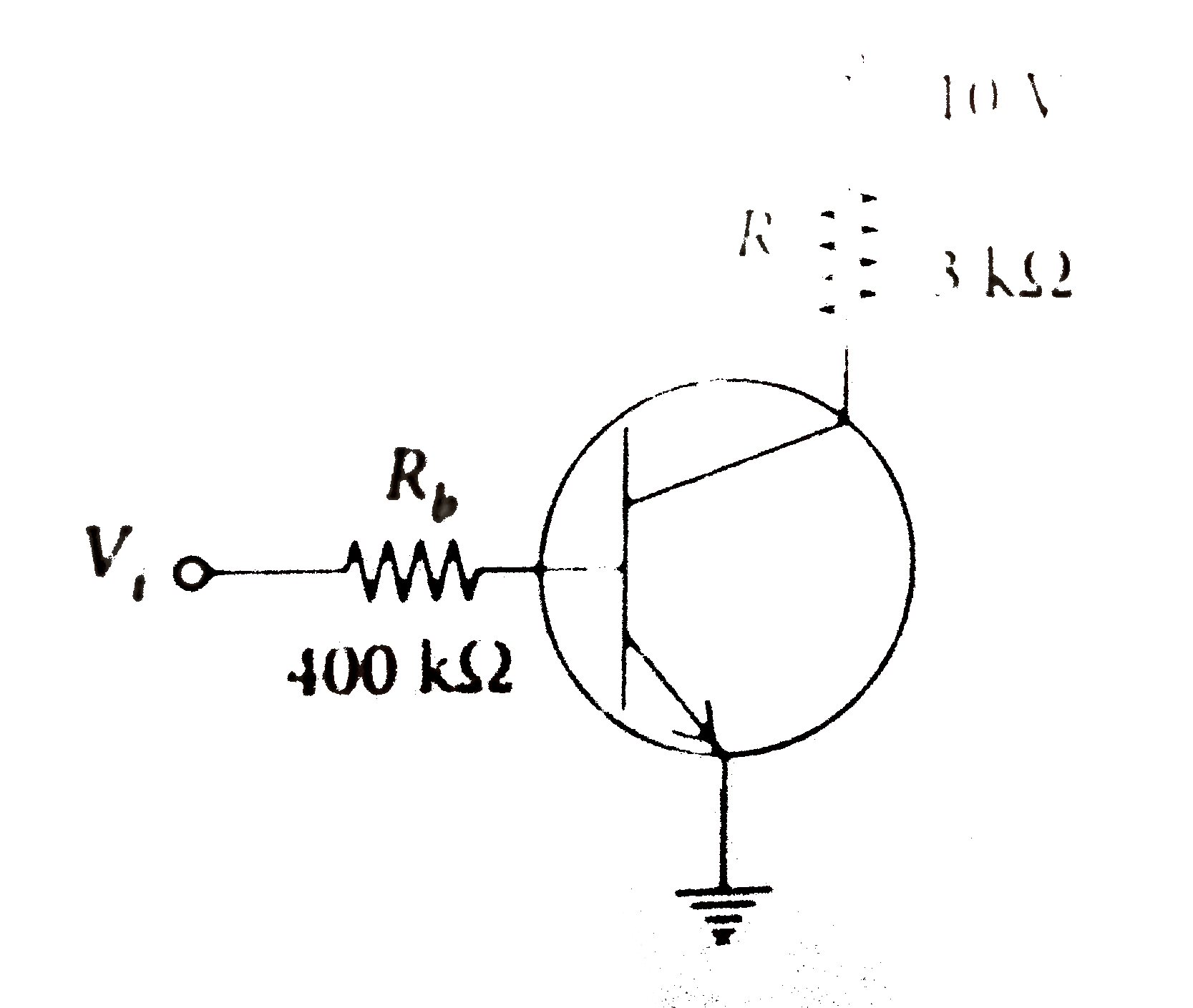
In the circuit shown in the figure, the input voltage Vi is 20V,VBE=0 and VCE=0. The values of IB,IC and β are given by:
A
IB=20μA,Ic=5mA,β=250
B
IB=25μA,Ic=5mA,β=200
C
IB=40μA,Ic=10mA,β=250
D
IB=40μA,IC=5mA,β=125
Video Solution
Text Solution
Voltage across base and emitter V∃=0
Voltage across collector and emitter VCE=0
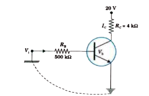
Applying Kirchoff law between C and E
20−IcRc−Vb=0
Ic=(20−04×103)⇒Ic=5×10−3=5mA
Applying Kirchoff .s law between B and E
V1−IB−Vb=−0
IB=20500×103=40μA
β=IcIb=25×10340×10−4=125
Hence option (d ) is correct
|
Updated on:21/07/2023
Topper's Solved these Questions
- BOOK - MODERN PUBLICATIONCHAPTER - SEMICONDUCTOR ELECTRONICS METERIALS DEVICES AND SIMPLE CIRCUITS EXERCISE - COMPETION FILE (JEE(MAIN) & OTHER STATE BOARDS FOR ENGINEERING ENTRANCE )31videos
SEMICONDUCTOR ELECTRONICS METERIALS DEVICES AND SIMPLE CIRCUITS
- BOOK - MODERN PUBLICATIONCHAPTER - SEMICONDUCTOR ELECTRONICS METERIALS DEVICES AND SIMPLE CIRCUITS EXERCISE - COMPETION FILE( MULTIPLE CHOICE QUESTIONS )17videos
SEMICONDUCTOR ELECTRONICS METERIALS DEVICES AND SIMPLE CIRCUITS
- BOOK - MODERN PUBLICATIONCHAPTER - SEMICONDUCTOR ELECTRONICS METERIALS DEVICES AND SIMPLE CIRCUITS EXERCISE - REVISION EXERCISES (NUMERICAL PROBLEMS )15videos
SEMICONDUCTOR ELECTRONICS METERIALS DEVICES AND SIMPLE CIRCUITS
- BOOK - MODERN PUBLICATIONCHAPTER - RAY OPTICS AND OPTICAL INSTRUMENTSEXERCISE - CHAPTER PRACTICE TEST14videos
RAY OPTICS AND OPTICAL INSTRUMENTS
- BOOK - MODERN PUBLICATIONCHAPTER - WAVE OPTICALEXERCISE - CHAPTER PRACTICE TEST7videos
WAVE OPTICAL
Similar Questions
Knowledge Check
- Question 1 - Select One
In the circuit shown in the figure, the input voltage Vi is 20V,VBE=0 and VCE=0. The values of IB,IC and β are given by:
 AIB=40μA,IC=10mA,β=250BIB=25μA,IC=5mA,β=200CIB=20μA,IC=5mA,β=250DIB=40μA,IC=5mA,β=125
 - Question 2 - Select One
In the circuit shows in the figure, the input voltage
Vi is 20 V, VBE=0 and VCE=0. The values of lB,lC and β are given by
 AlB=20μA,lC=5mA,β=250BlB=25μA,lC=5mA,β=200ClB=40μA,lC=10mA,β=250DlB=40μA,lC=5mA,β=125
 - Question 3 - Select One
In the circuit shown in figure the maximum output voltage V0 is
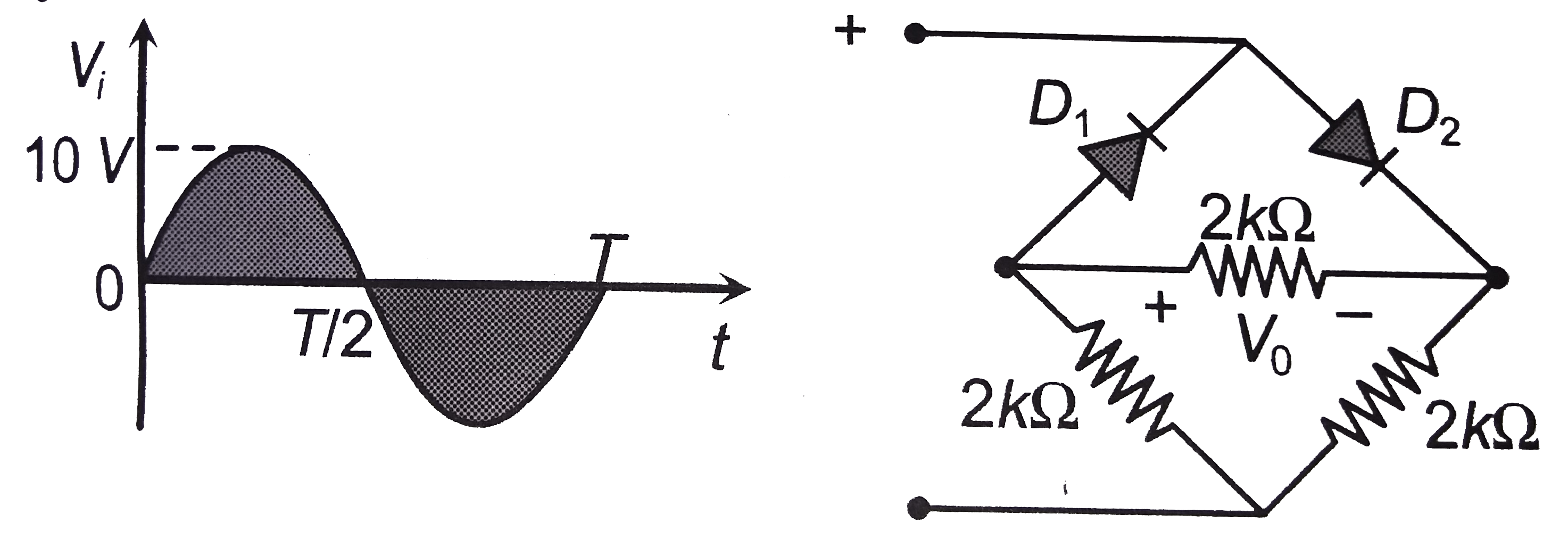 A0VB5VC10VD5√2V
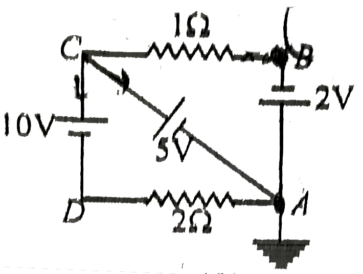
In the circuit shown in the figure, the ratio of VB as VC is
 View Solution
In the circuit shown in the figure, the input voltage Vi is 20V,VBE=0 and VCE=0. The values of IB,IC and β are given by:
 View Solution
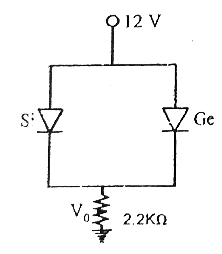
In the circuit shown in figure, Voltage V0 is
 View Solution
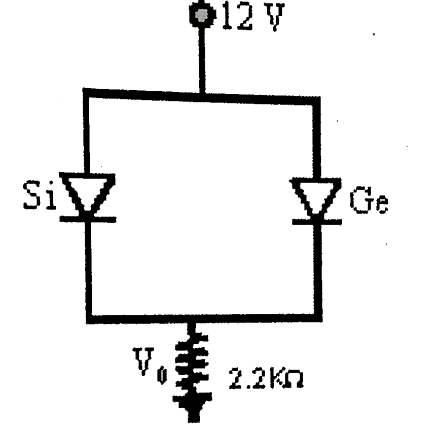
In the circuit shown infigure, voltage V0 is,View SolutionIn the circuit shown in figure, when the input voltage of the base resistance is 10 V, Vbe is zero and Vce is also zero. Then
 View Solution


