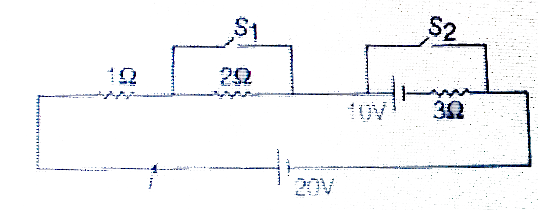
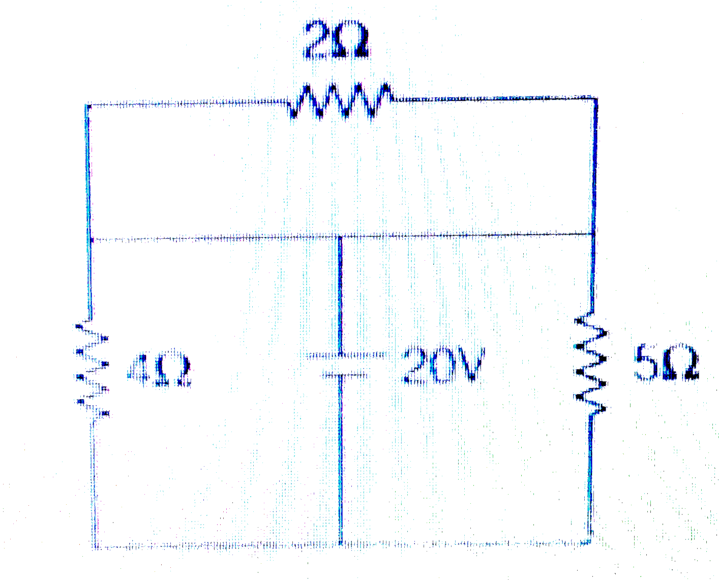
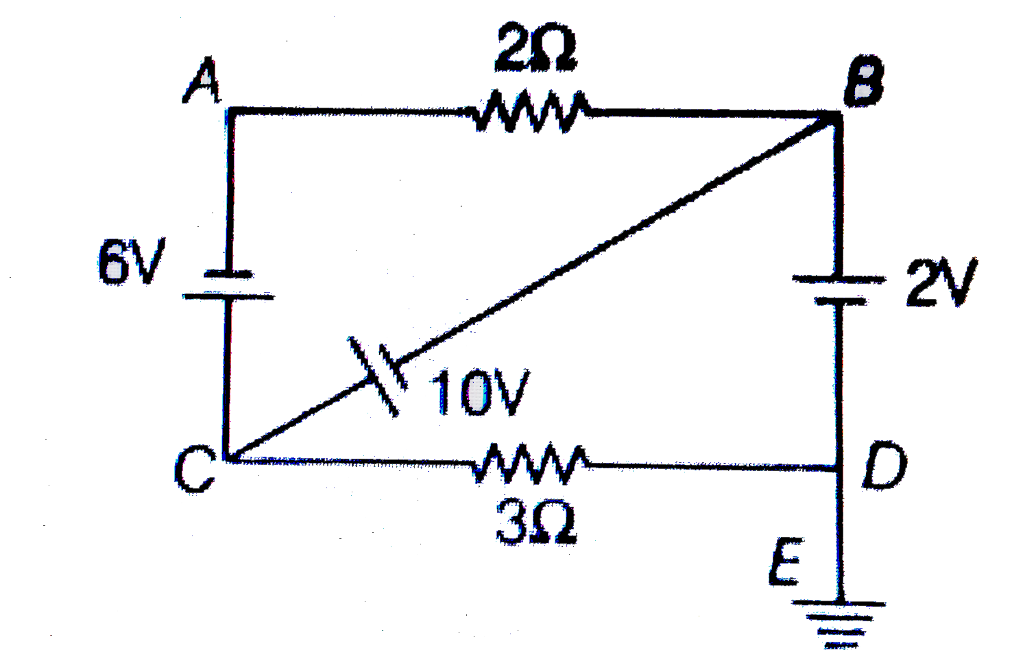
In the diode circuit shown in figure,

A
D1andD2 are reverse biased
B
D1andD2 are forward biased
C
D1 is forward biased and D2 is reverse biased.
D
D1 is reverse biased and D2 is forward biased.
Video Solution
Text Solution
The correct Answer is:C
|
Answer
Step by step video & text solution for In the diode circuit shown in figure, by Physics experts to help you in doubts & scoring excellent marks in Class 12 exams.
Updated on:21/07/2023Topper's Solved these Questions
- ELECTRONIC DEVICESBOOK - MTG GUIDECHAPTER - ELECTRONIC DEVICESEXERCISE - CHECK YOUR BEET VITALS
25 Videos
- ELECTRONIC DEVICESBOOK - MTG GUIDECHAPTER - ELECTRONIC DEVICESEXERCISE - AIPMT/NEET (MCQs)
42 Videos
- ELECTRONIC DEVICESBOOK - MTG GUIDECHAPTER - ELECTRONIC DEVICESEXERCISE - AIPMT/NEET (MCQs)
42 Videos
- ELECTROMAGNETIC WAVESBOOK - MTG GUIDECHAPTER - ELECTROMAGNETIC WAVESEXERCISE - AIPMT/NEET(MCQs)
15 Videos
- ELECTROSTATICSBOOK - MTG GUIDECHAPTER - ELECTROSTATICSEXERCISE - AIPMT/NEET (MCQ.s)
34 Videos
Similar Questions
Knowledge Check
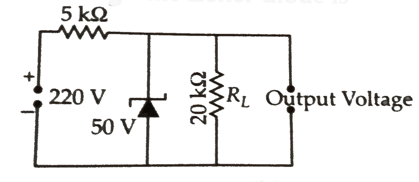
From the Zener diode circuit shown in figure, the current through the Zener diode is
 A34 mAB31.5 mAC36.5 mAD2.5 mA
From the Zener diode circuit shown in figure, the current through the Zener diode is
 A34 mAB31.5 mAC36.5 mAD2.5 mA
In the two circuits shown in figure
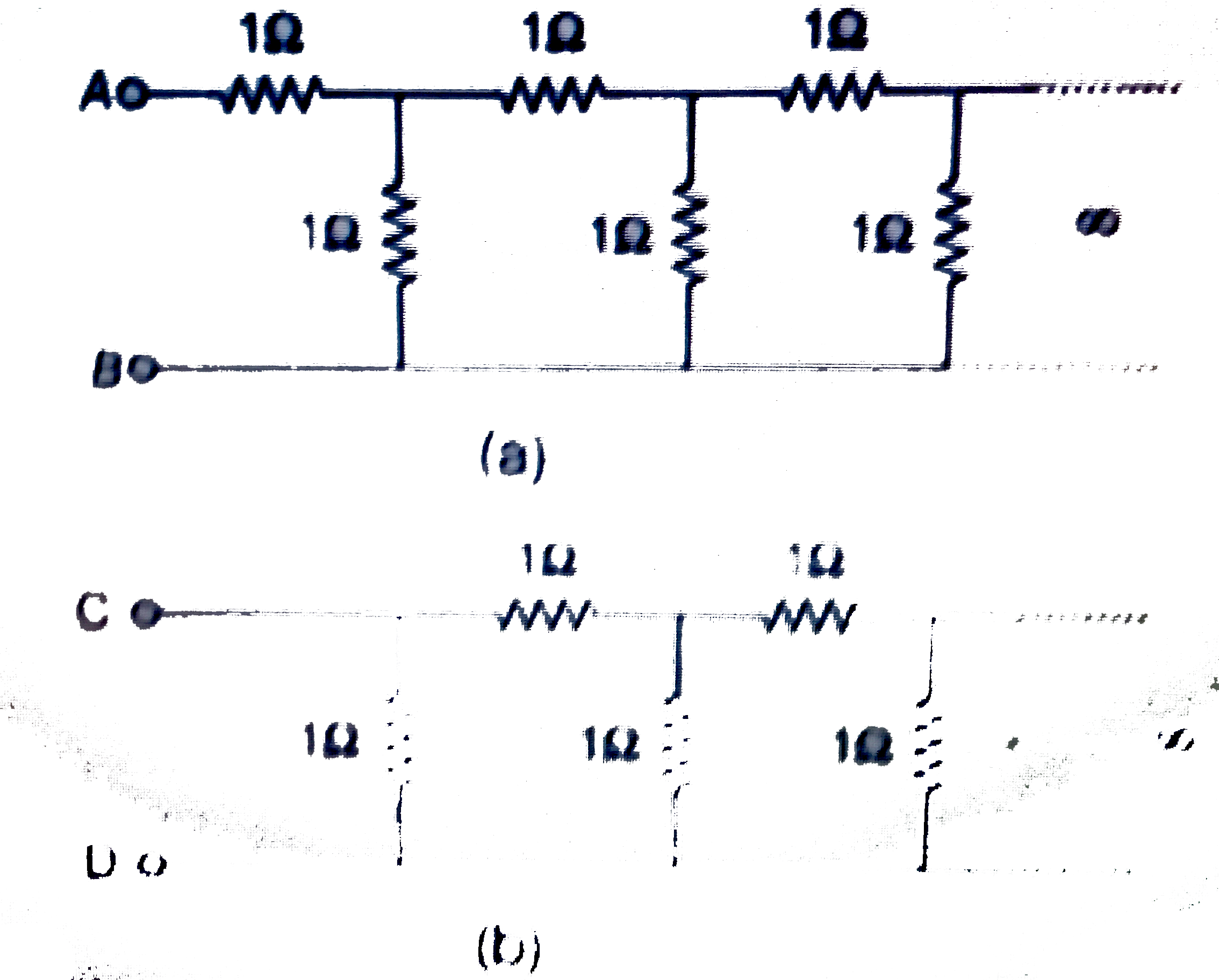 ARAB=RCD=(√3+2)ΩBRAB=(√3+1)ΩCRCD=(√5+1)ΩDRAB>RCD

