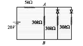
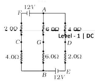
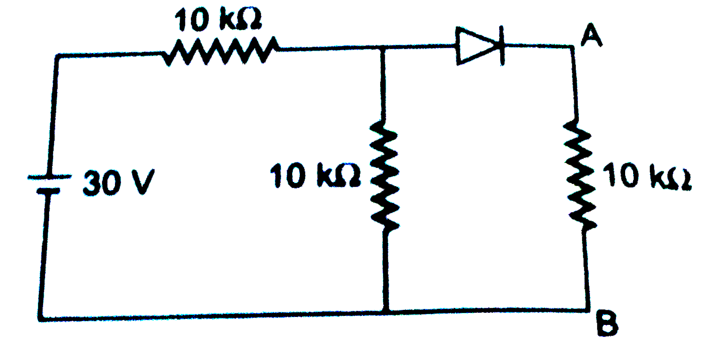
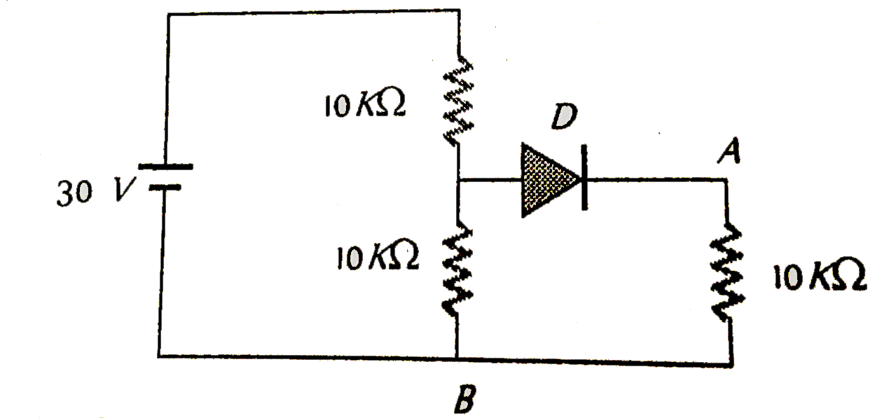
In the figure, potential difference between A and B is
A
zero
B
5 V
C
10 V
D
15 V
Video Solution
Text Solution
The correct Answer is:C
Here p-n junction is forward biased. If p-n junction is ideal, its resistance is zero. The effective resistance across A and B
=10×1010+10=5KΩ
Current in the circuit, I=VR=3015×103=2103A
Current in arm AB=I=2103
Potential difference across A and B
=2103×5×103=10V
|
Topper's Solved these Questions
- SEMICONDUCTORSBOOK - MHTCET PREVIOUS YEAR PAPERS AND PRACTICE PAPERSCHAPTER - SEMICONDUCTORSEXERCISE - MHT CET Corner
25 Videos
- SEMICONDUCTORSBOOK - MHTCET PREVIOUS YEAR PAPERS AND PRACTICE PAPERSCHAPTER - SEMICONDUCTORSEXERCISE - Exercise 1 ( TOPICAL PROBLEMS )
84 Videos
- SCALARS AND VECTORS BOOK - MHTCET PREVIOUS YEAR PAPERS AND PRACTICE PAPERSCHAPTER - SCALARS AND VECTORS EXERCISE - Exercise 2 (Miscellaneous Problems)
20 Videos
- STATIONARY WAVES BOOK - MHTCET PREVIOUS YEAR PAPERS AND PRACTICE PAPERSCHAPTER - STATIONARY WAVES EXERCISE - MHT CET Corner
28 Videos
Similar Questions
Knowledge Check
In the figure, potential difference between A & B is
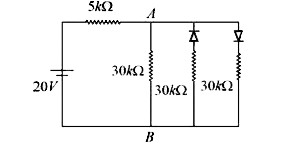 A5VB10VC15VD20V
The potential difference between A and B is
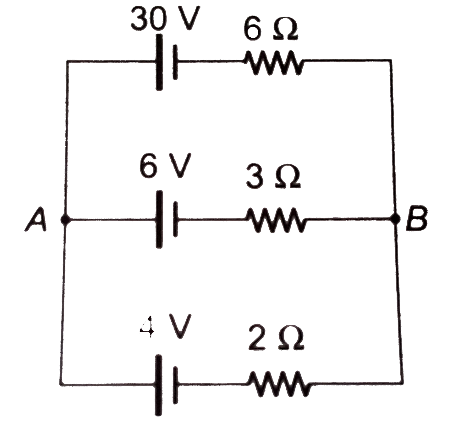 .A9 VB15 VC10 VD20 V
In the given figure, potential difference between A and B is
 A0B5 voltC10 voltD15 volt
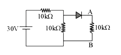
In the given figure potential difference between A and B is -
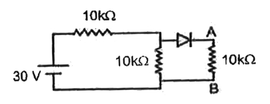
View SolutionIn the adjacent figure, the potential difference between A and B is
View SolutionIn the circuit shown in figure potential difference between A and B is

View Solution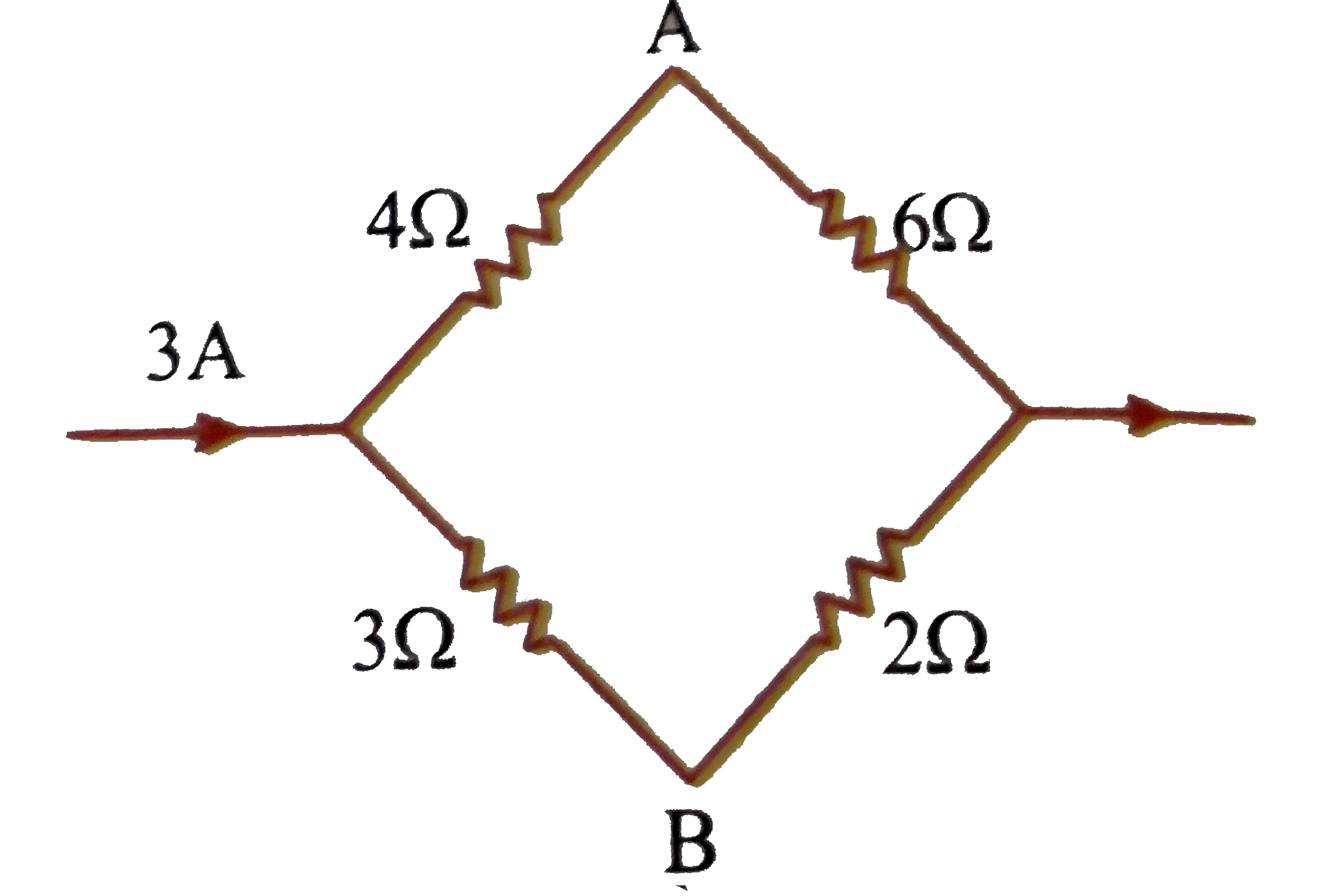
A current of 3A flows in a circuit shown in the figure. The potential difference between A and b is
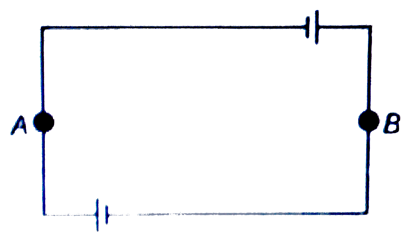
View SolutionTwo identical batteries, each having emf of 1.8 V and of equal internal resistances are connected as shown in the figure. Potential difference between A and B will be equal to (Ignore the resistance of lead wires)
View Solution

