The value of the resistor, RS, needed in the dc voltage regulator circuit shown here, equals :-
_E01_502_Q01.png)
(Vi−VL)(n+1)IL
(Vi+VL)(n+1)IL
(Vi−VL)nIL
(Vi−VL)nIL
The correct Answer is:A
Current through resistor, Rs=IL+nIL=(1+n)IL
In the voltage regulator circuit, the voltage across resistor Rs will be equal to the potential difference between input source and output load.
i.e. IsRs=Vi−VL⇒(1+n)ILRs=Vi−VL
So, value of the resistor, Rs=Vi−VL(n+1)IL
Topper's Solved these Questions
- BOOK - MHTCET PREVIOUS YEAR PAPERS AND PRACTICE PAPERSCHAPTER - SEMICONDUCTORSEXERCISE - MHT CET Corner25videos
SEMICONDUCTORS
- BOOK - MHTCET PREVIOUS YEAR PAPERS AND PRACTICE PAPERSCHAPTER - SEMICONDUCTORSEXERCISE - Exercise 1 ( TOPICAL PROBLEMS )84videos
SEMICONDUCTORS
- BOOK - MHTCET PREVIOUS YEAR PAPERS AND PRACTICE PAPERSCHAPTER - SCALARS AND VECTORS EXERCISE - Exercise 2 (Miscellaneous Problems)20videos
SCALARS AND VECTORS
- BOOK - MHTCET PREVIOUS YEAR PAPERS AND PRACTICE PAPERSCHAPTER - STATIONARY WAVES EXERCISE - MHT CET Corner28videos
STATIONARY WAVES
Similar Questions
A zener diode has a breakdown voltage of 10 V and is used in a voltage regulator circuit as shown in the given figure what will be current through the diode
 View Solution
A zener diode having breakdown voltage equal to 15V, is used in a voltage regulator circuit shown in figure. Find the current through the diode.
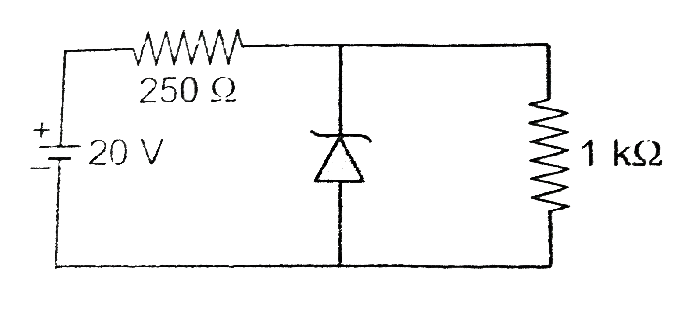 View Solution
Knowledge Check
- Question 1 - Select One
A zener diode, having breakdown voltage equal to 15V is used in a voltage regulator circuit shown in the figure. The current through the diode is
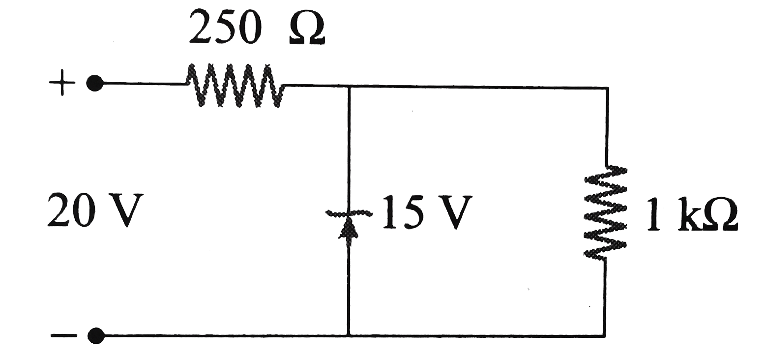 A10mAB15mAC20mAD5mA
 - Question 2 - Select One
The value of R in the circuit shown in the figure is
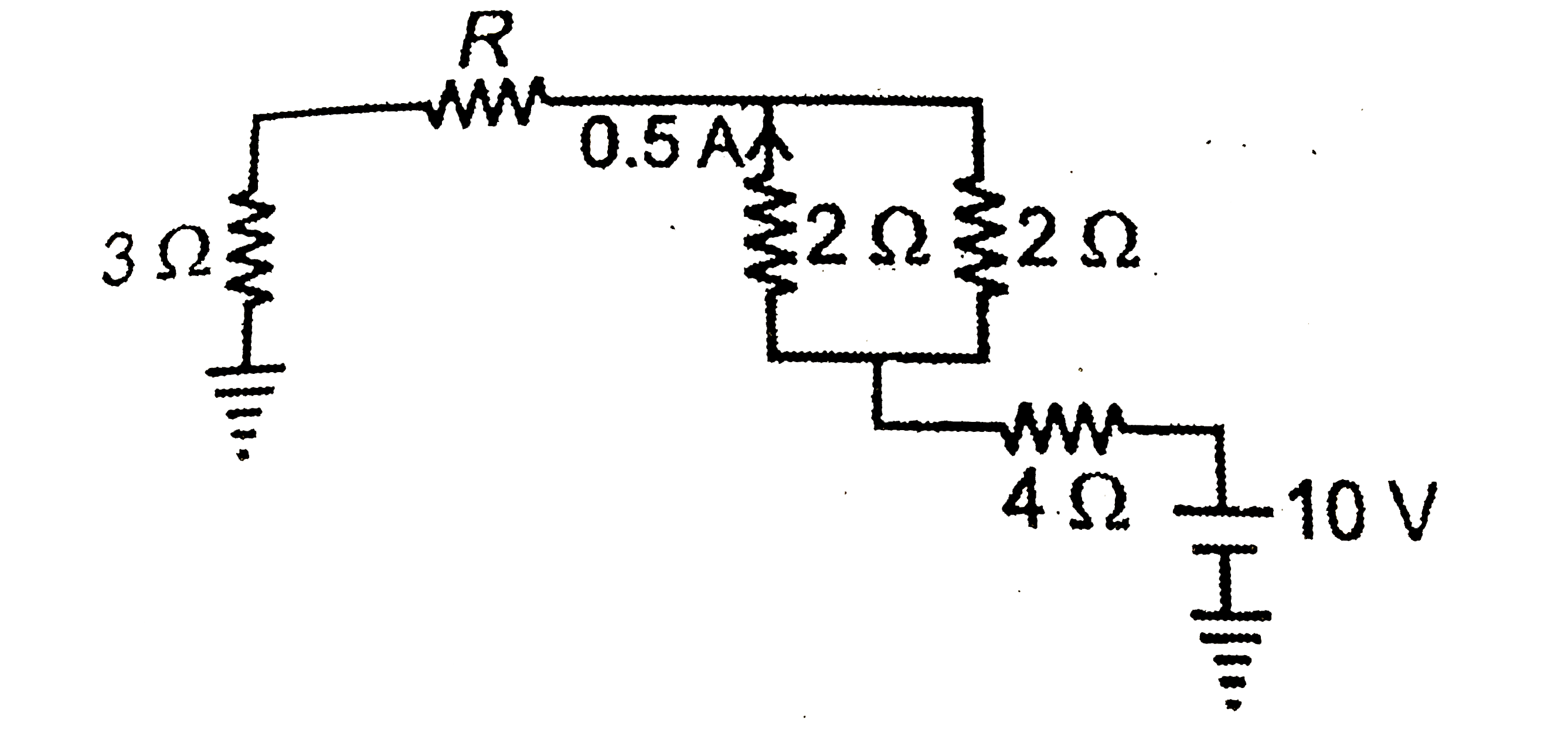 A2ΩB3ΩC4ΩD1Ω
 - Question 3 - Select One
In the circuit shown here, what is the value of the unknown resistor R so that the total resistance of the circuit between points P and Q is also equal to R
 A3 ohmsB√39 ohmsC√69 ohmsD10 ohms
In the circuit shown in figure, the value of R is
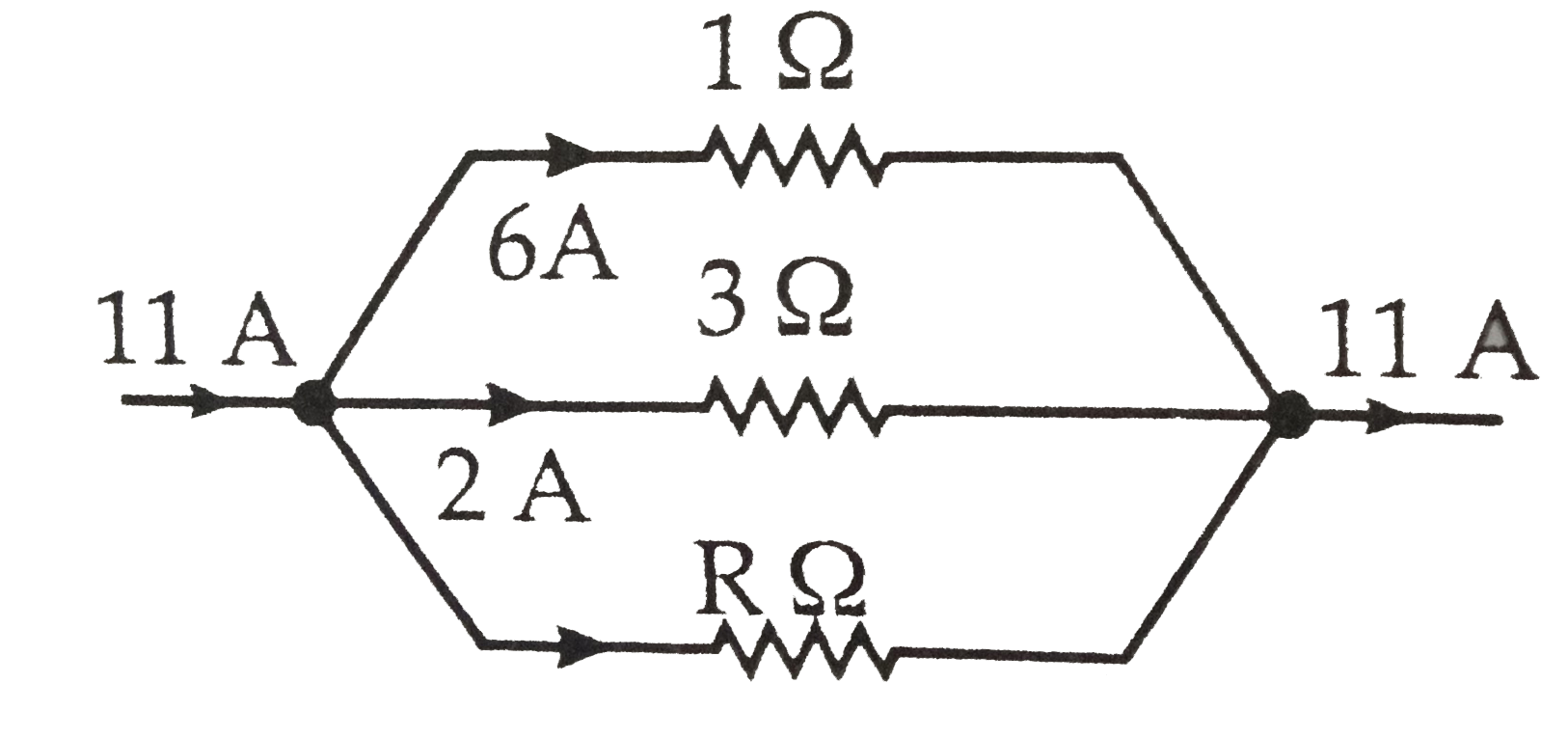 View Solution
In an experiment to find the equivalent resistance of a series combination of two resistors R1 and R2,a student uses the circuit shown here. Will the circuit give the correct reading for current I and voltage V ? Justify your answer.
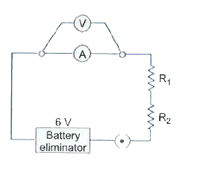 View Solution
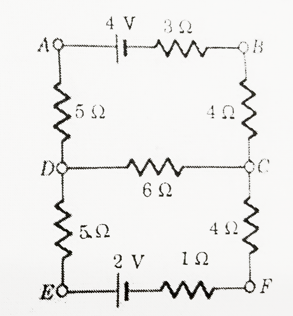
Calculate (i) current in the 6Ω resistor, (ii) terminal voltage across the 4V cell in the circuit shown in figure.View SolutionA zener diode, having breakdown voltage equal to 15V is used in a voltage regulator circuit shown in the figure. The current through the diode is
 View Solution
The circuit shown here is logically equivalent to :-
_E01_424_Q01.png) View Solution
View Solution

