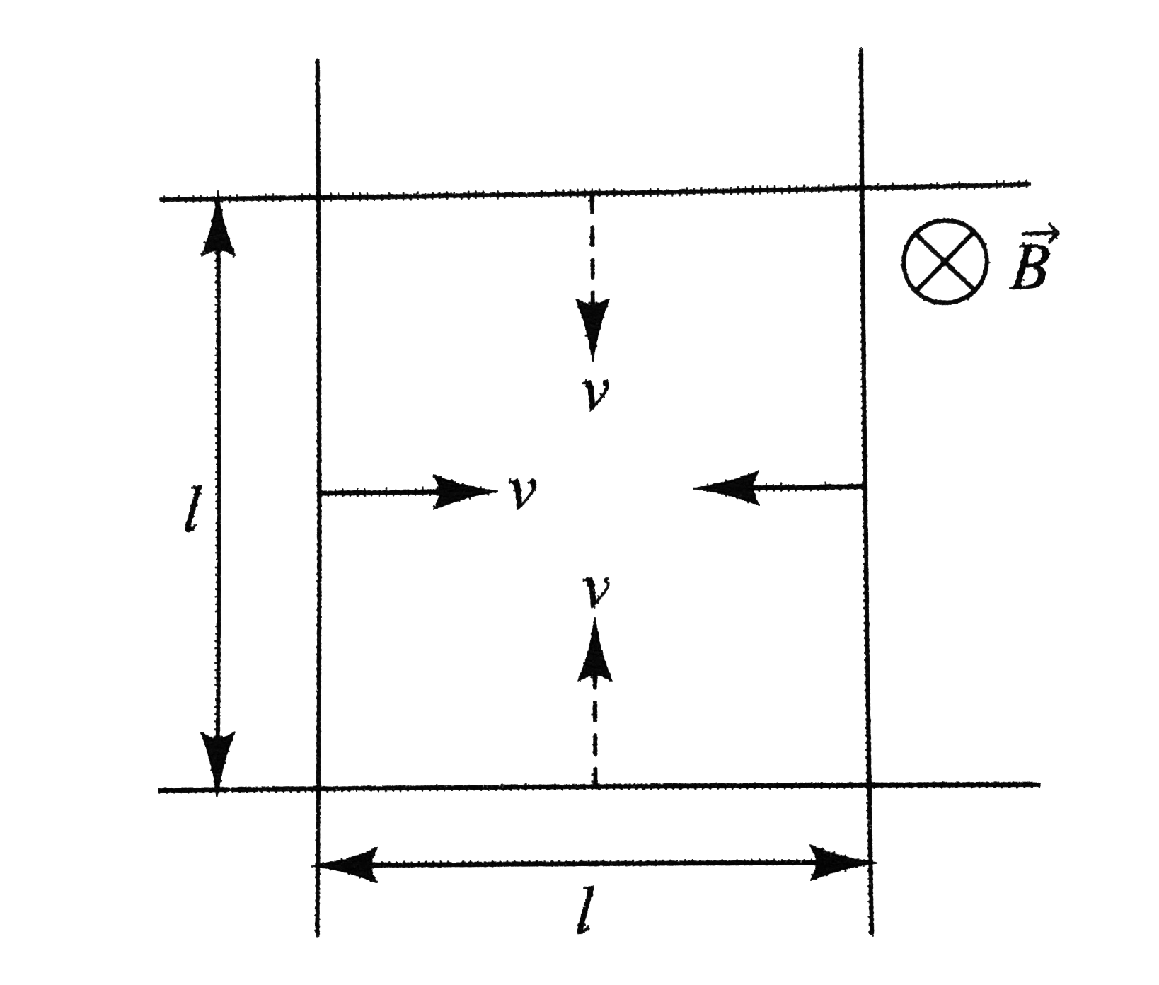
In the figure shown the four rods have λ resistance per unit length . The arrangement is kept in a magnetic field of constant magnitude B and directed perpendicular to the plane of the figure and direction inwards . Initially the sides as shown form a square . Now each wire starts moving with constant velocity v towards opposite wire . Find as a function of time .

Total power required to maintain constant velocity .
4B2v2λ(l+2vt)
4B2v2λ(l−vt)
4B2v2λ(l−2vt)
B2v2λ(l−2vt)
The correct Answer is:c
Topper's Solved these Questions
- ELECTROMAGNETIC INDUCTIONBOOK - CENGAGE PHYSICSCHAPTER - ELECTROMAGNETIC INDUCTIONEXERCISE - single correct
8 Videos
- ELECTROMAGNETIC INDUCTIONBOOK - CENGAGE PHYSICSCHAPTER - ELECTROMAGNETIC INDUCTIONEXERCISE - comprehensive type
7 Videos
- ELECTROMAGNETIC INDUCTIONBOOK - CENGAGE PHYSICSCHAPTER - ELECTROMAGNETIC INDUCTIONEXERCISE - single correct
10 Videos
- ELECTROMAGENTIC INDUCTIONBOOK - CENGAGE PHYSICSCHAPTER - ELECTROMAGENTIC INDUCTIONEXERCISE - QUESTION BANK
40 Videos
- ELECTRON,PHONTS,PHOTOELECTRIC EFFECT & X-RAYSBOOK - CENGAGE PHYSICSCHAPTER - ELECTRON,PHONTS,PHOTOELECTRIC EFFECT & X-RAYSEXERCISE - dpp 3.3
15 Videos
Similar Questions
In the figure shown the four rods have λ resistance per unit length . The arrangement is kept in a magnetic field of constant magnitude B and directed perpendicular to the plane of the figure and direction inwards . Initially the sides as shown form a square . Now each wire starts moving with constant velocity v towards opposite wire . Find as a function of time .

Thermal power developed in the circuit.
View SolutionIn the figure shown the four rods have λ resistance per unit length . The arrangement is kept in a magnetic field of constant magnitude B and directed perpendicular to the plane of the figure and direction inwards . Initially the sides as shown form a square . Now each wire starts moving with constant velocity v towards opposite wire . Find as a function of time .

Force required on each wire to keep its velocity constant .
View Solution
Knowledge Check
In the figure shown the four rods have λ resistance per unit length . The arrangement is kept in a magnetic field of constant magnitude B and directed perpendicular to the plane of the figure and direction inwards . Initially the sides as shown form a square . Now each wire starts moving with constant velocity v towards opposite wire . Find as a function of time .

Thermal power developed in the circuit.A4B2v2λ(l−2vt)B4B2v2λ(l−vt)C4B2v2λ(l+2vt)DB2v2λ(l−2vt)In the figure shown the four rods have λ resistance per unit length . The arrangement is kept in a magnetic field of constant magnitude B and directed perpendicular to the plane of the figure and direction inwards . Initially the sides as shown form a square . Now each wire starts moving with constant velocity v towards opposite wire . Find as a function of time .

Force required on each wire to keep its velocity constant .AB2vλ(l+2vt)BB2vλ(l−vt)CzeroDB2vλ(l−2vt)In the figure shown the four rods have λ resistance per unit length . The arrangement is kept in a magnetic field of constant magnitude B and directed perpendicular to the plane of the figure and direction inwards . Initially the sides as shown form a square . Now each wire starts moving with constant velocity v towards opposite wire . Find as a function of time .

Induced current in the circuit with directionA2BvλBBvλCBv2λDzero
In the figure shown the four rods have λ resistance per unit length . The arrangement is kept in a magnetic field of constant magnitude B and directed perpendicular to the plane of the figure and direction inwards . Initially the sides as shown form a square . Now each wire starts moving with constant velocity v towards opposite wire . Find as a function of time .

Induced current in the circuit with direction
View SolutionIn the figure shown the four rods have λ resistance per unit length. The arrangement is kept in a magnetic filed of constant magnitude B and directed perpendicular to the plane of the figure and direction inwards. Intially the sides as shown from a square. Now each wire starts moving with constant velocity v towards opposite wire. Find as a function of time:
(a) induced emf in the circuit
(b) induced current in the circuit with direction

View Solutionin fig. The four rods have λ resistance per unit length. The arrengement is kept in a magnetic field of constant magnitude B and directed perpendicular to the plane of the figure and directing in ward. Initially, the sides as shown form a square. Now each wire starts moving with constant velocity v toward the opposite wire.
Find as a function of time:
(a) induced emf in the circuit.
(b) induced current in the circuit with direction.
( c ) force required on each wire to keep its velocity consatnt.
(d) total power required to maintain constant velocity.
(e) thermal power developed in the circuit.

View Solution
