In the given circuit (as shown in fig. 5.319).
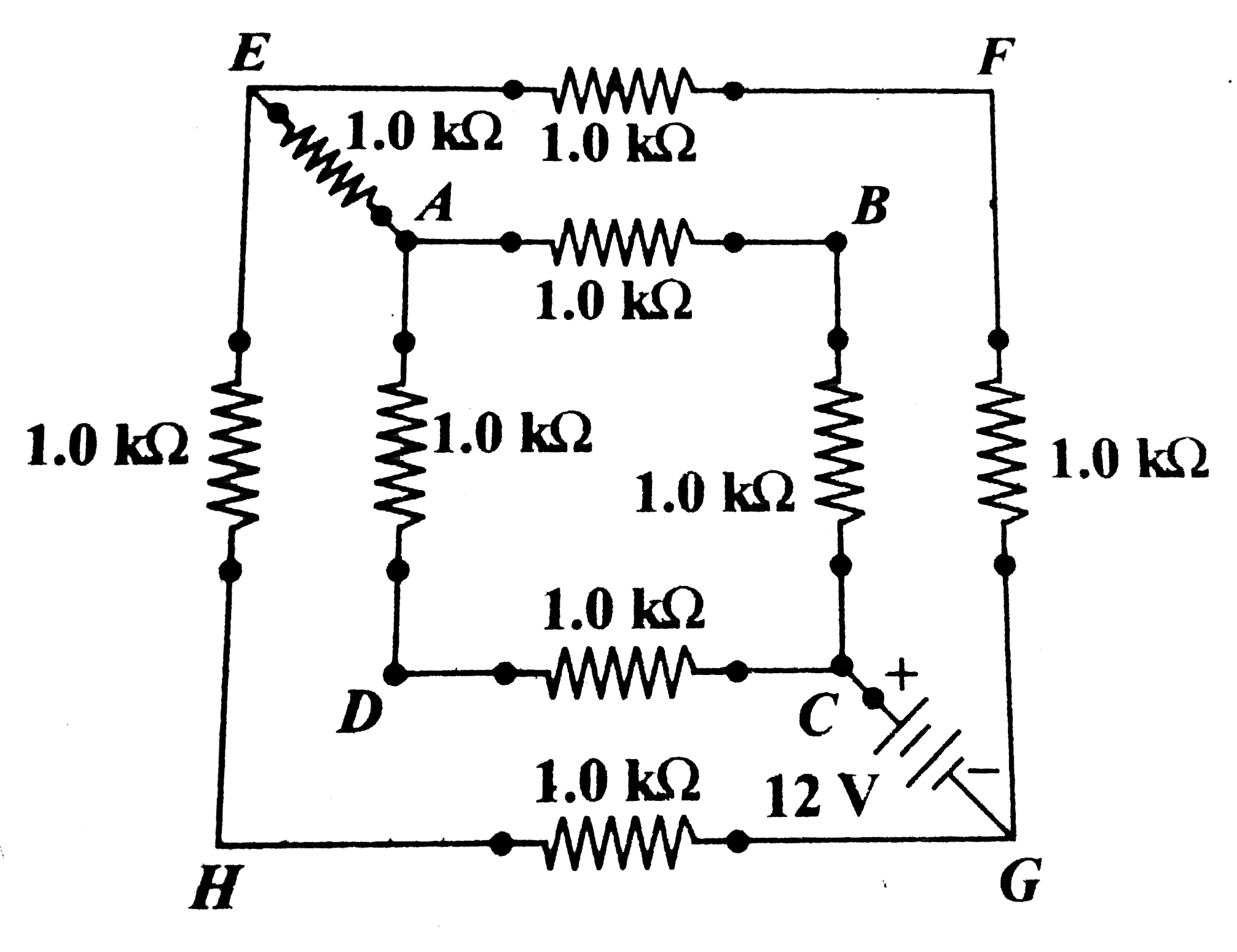
the equivalent resistance between C and G is 3Kω
the current provided by the source is 4 mA
the current provided by the source is 8mA
voltage across points G and E is 4V
The correct Answer is:A, B, D
The circuit can be redrawn as shown in the figure.
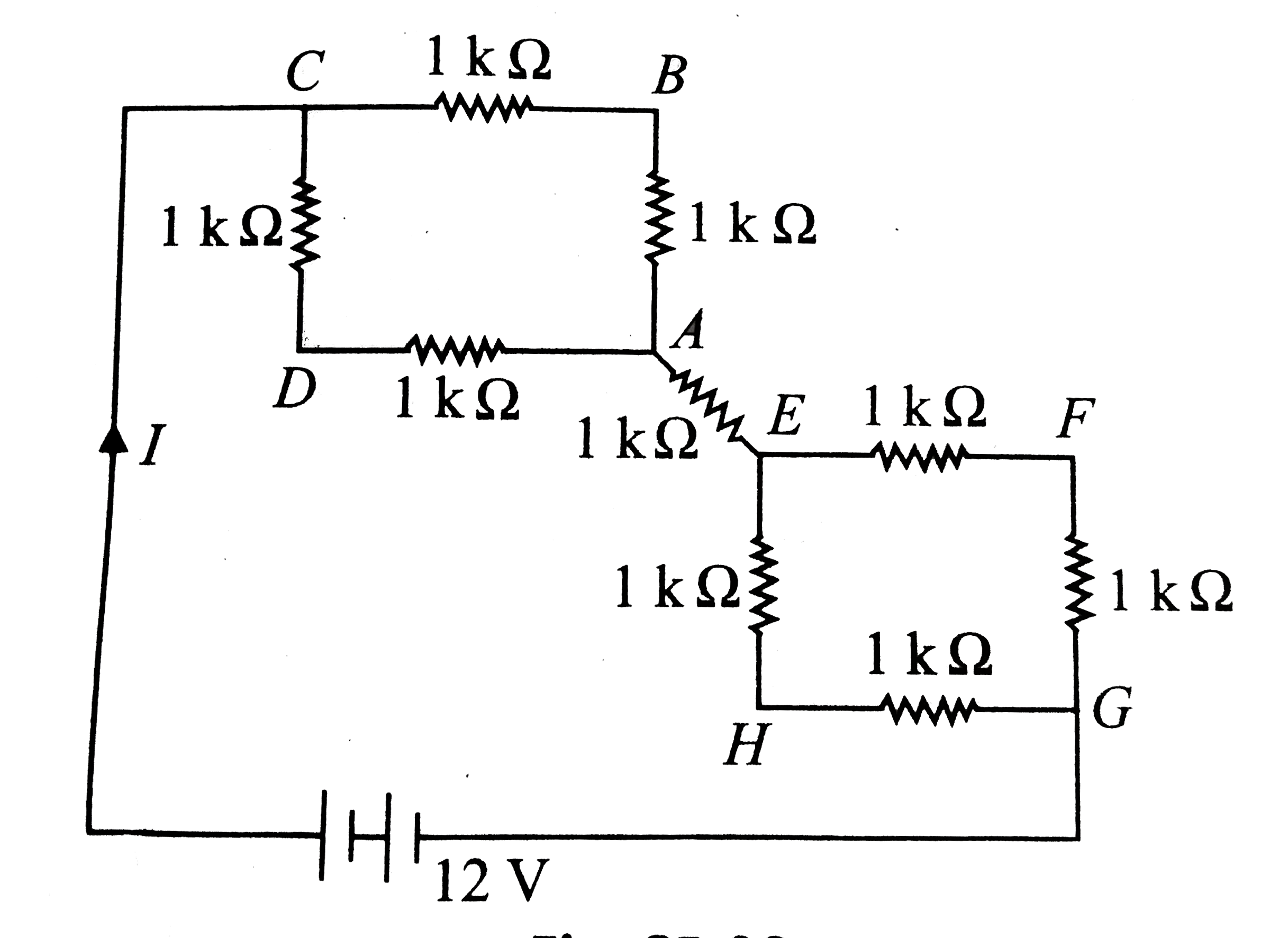
Req=3kΩ,I=123×103=4mA
VE−VG=I(1kΩ)=4×10−3×1x103=4V
Topper's Solved these Questions
- BOOK - CENGAGE PHYSICS ENGLISHCHAPTER - ELECTRIC CURRENT AND CIRCUITEXERCISE - Comprehension35videos
ELECTRIC CURRENT AND CIRCUIT
- BOOK - CENGAGE PHYSICS ENGLISHCHAPTER - ELECTRIC CURRENT AND CIRCUITEXERCISE - Interger8videos
ELECTRIC CURRENT AND CIRCUIT
- BOOK - CENGAGE PHYSICS ENGLISHCHAPTER - ELECTRIC CURRENT AND CIRCUITEXERCISE - Single Correct72videos
ELECTRIC CURRENT AND CIRCUIT
- BOOK - CENGAGE PHYSICS ENGLISHCHAPTER - ELECTRIC CURRENT & CIRCUITSEXERCISE - Kirchhoff s law and simple circuits15videos
ELECTRIC CURRENT & CIRCUITS
- BOOK - CENGAGE PHYSICS ENGLISHCHAPTER - ELECTRIC FLUX AND GAUSS LAWEXERCISE - MCQ s38videos
ELECTRIC FLUX AND GAUSS LAW
Similar Questions
In the given circuit (as shown in the figure)View SolutionIn the circuit shown in Fig. 7.45,
 View Solution
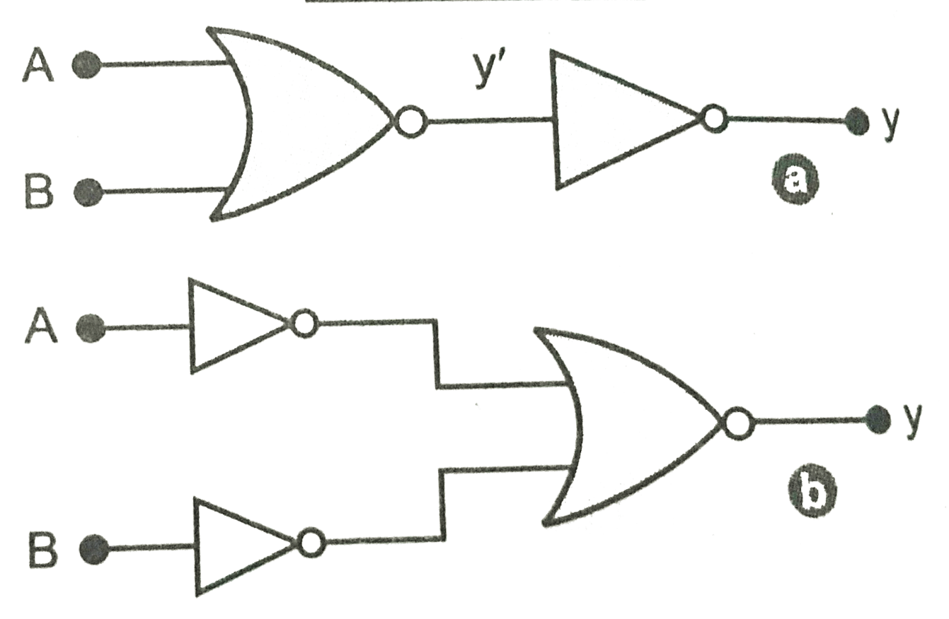
You are given the two circuits as shown in Fig. and . Show that circuit acts as OR gate while the circuit acts as AND gate.
 View Solution
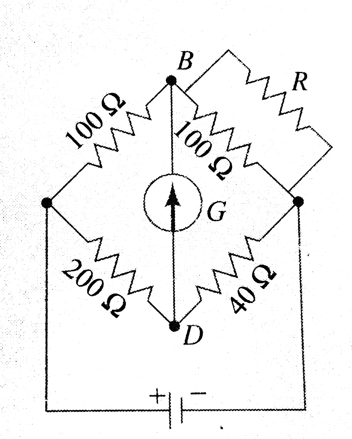
Find the current in each resistor in the circuit as shown in fig.
 View Solution
The potential difference between points A and B in the circuit shown in fig. 5.317 is 16V. Then
 View Solution
For the given circuit shown in figure below, time constant is
 View Solution
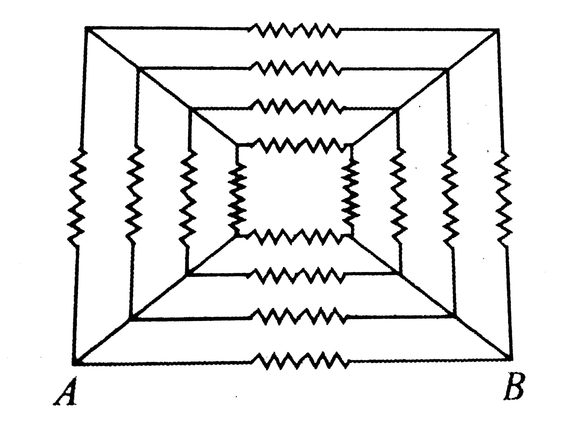
Sixteen resistor, each resistane 16Ω are connected in the circuit as shown in fig. the net resistance between A and B is
 View Solution
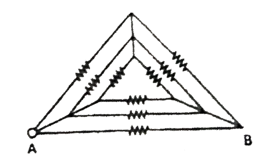
Nine resistors each of resistance R are connected in the circuit as shown in fig. The net resistance between A and B is
 View Solution
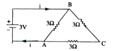
The current .i. in the circuit as shown in fig. is
 View Solution
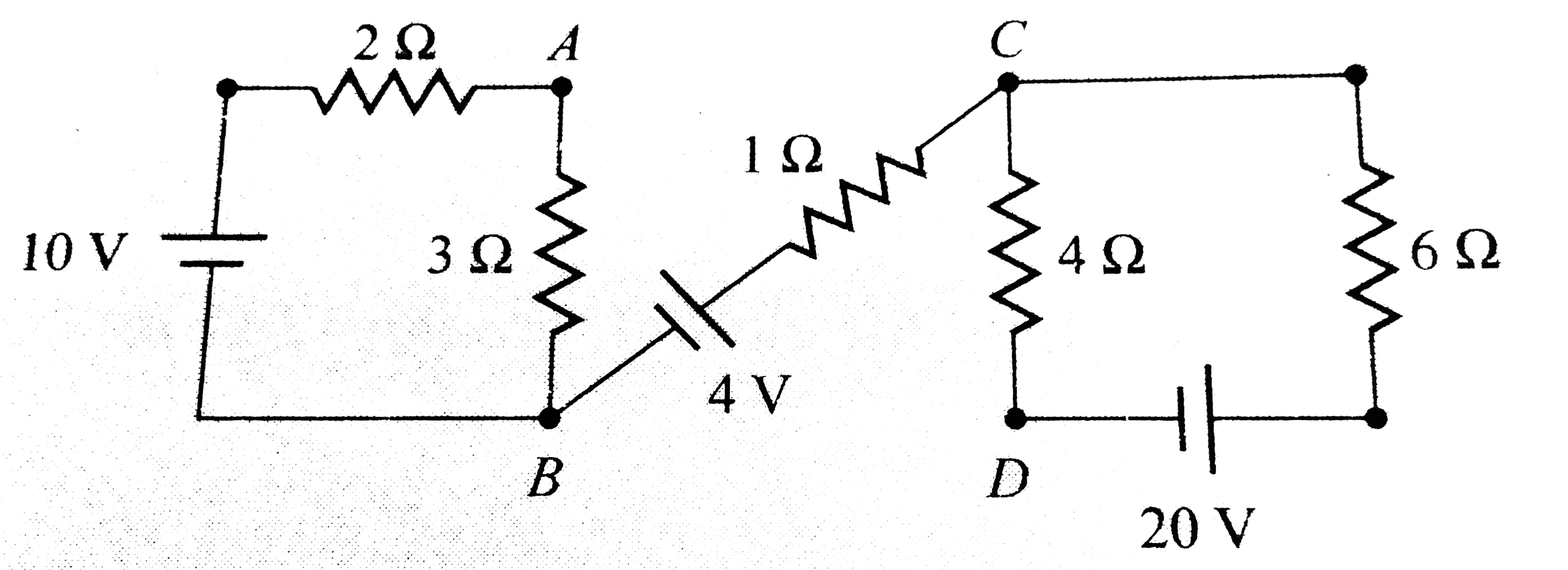
In the circuit shown in Fig. 5.79, determine the voltage drop between A and D.
 View Solution

