In the circuit shown in Fig. 5.79, determine the voltage drop between A and D.
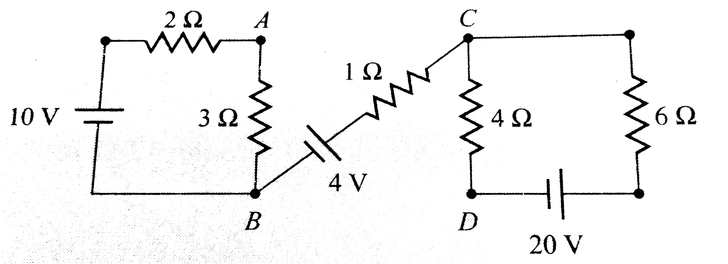
We need to divide this circuit inot three parts. We have left
loop, right loop, and the central part. To find out voltage drop
between points A and D, we have to apply Kirchhoff's second
law to these circuits one by one.
Also let us assume that Curretn I1 flows in the left circuit in
the clockwise direciton and curretnI2 flows in the right circuit in the anticlockwise direction.
Direction of both th currents is decided by the battery
presnet in the circuit as current flows from positve to negative.
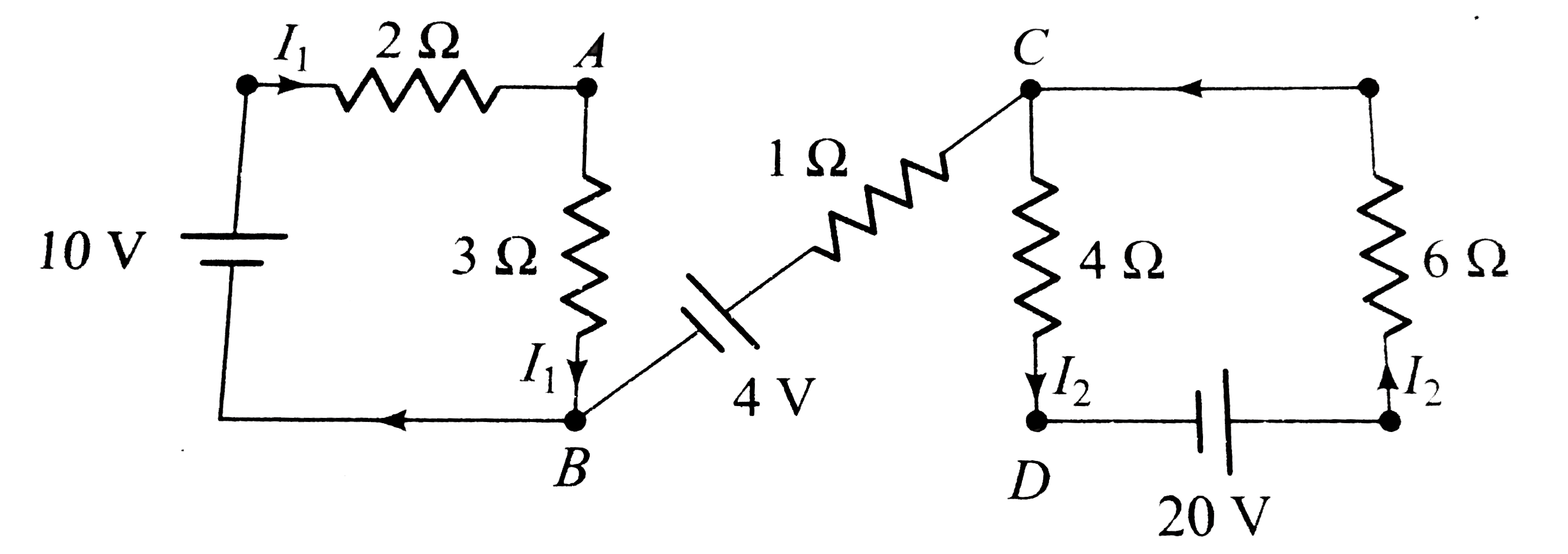
Applying Kirchhoff's second law to left loop, we get
=−2I1−3l1+10=0or−5I1=−10orI1=2A
Now applying Kirchhoff's second law to right loop, we get
4I2+6I2−20=0or10I2=20orI2=2A
Applying the law between points A and D, we get
VA−3I1+4−4I2=VDorVA−VD=3I1+4I2−4
Putting values of I1andI2 in the above expression, we get
VA−VD=3×2+4×2−4=6+8−4=10V
Topper's Solved these Questions
- BOOK - CENGAGE PHYSICS ENGLISHCHAPTER - ELECTRIC CURRENT AND CIRCUITEXERCISE - Solved Examples12videos
ELECTRIC CURRENT AND CIRCUIT
- BOOK - CENGAGE PHYSICS ENGLISHCHAPTER - ELECTRIC CURRENT AND CIRCUITEXERCISE - Exercise 5.128videos
ELECTRIC CURRENT AND CIRCUIT
- BOOK - CENGAGE PHYSICS ENGLISHCHAPTER - ELECTRIC CURRENT & CIRCUITSEXERCISE - Kirchhoff s law and simple circuits15videos
ELECTRIC CURRENT & CIRCUITS
- BOOK - CENGAGE PHYSICS ENGLISHCHAPTER - ELECTRIC FLUX AND GAUSS LAWEXERCISE - MCQ s38videos
ELECTRIC FLUX AND GAUSS LAW
Similar Questions
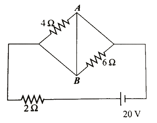
In the circuit shown in Fig. 7.45,
 View Solution
For the circuit shown in figure, determine the voltage across 4Ω resistors in volt ?
 View Solution
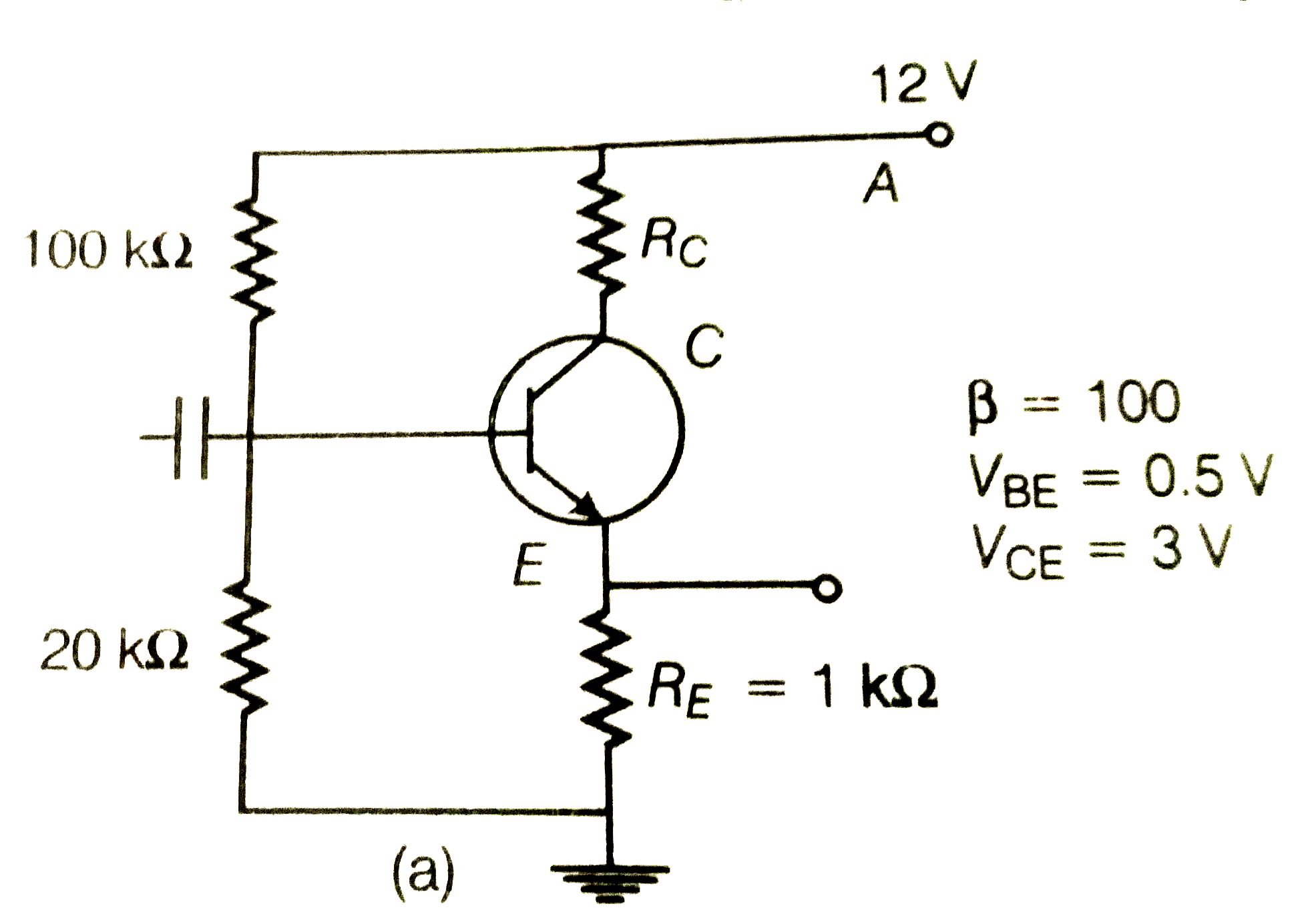
In the circuit shown in fig. (a), final the value of RC.
 View Solution
In the circuit shown in fig. some potential difference is applied between A and B. The equivalent resistance between A and B is R.
 View Solution
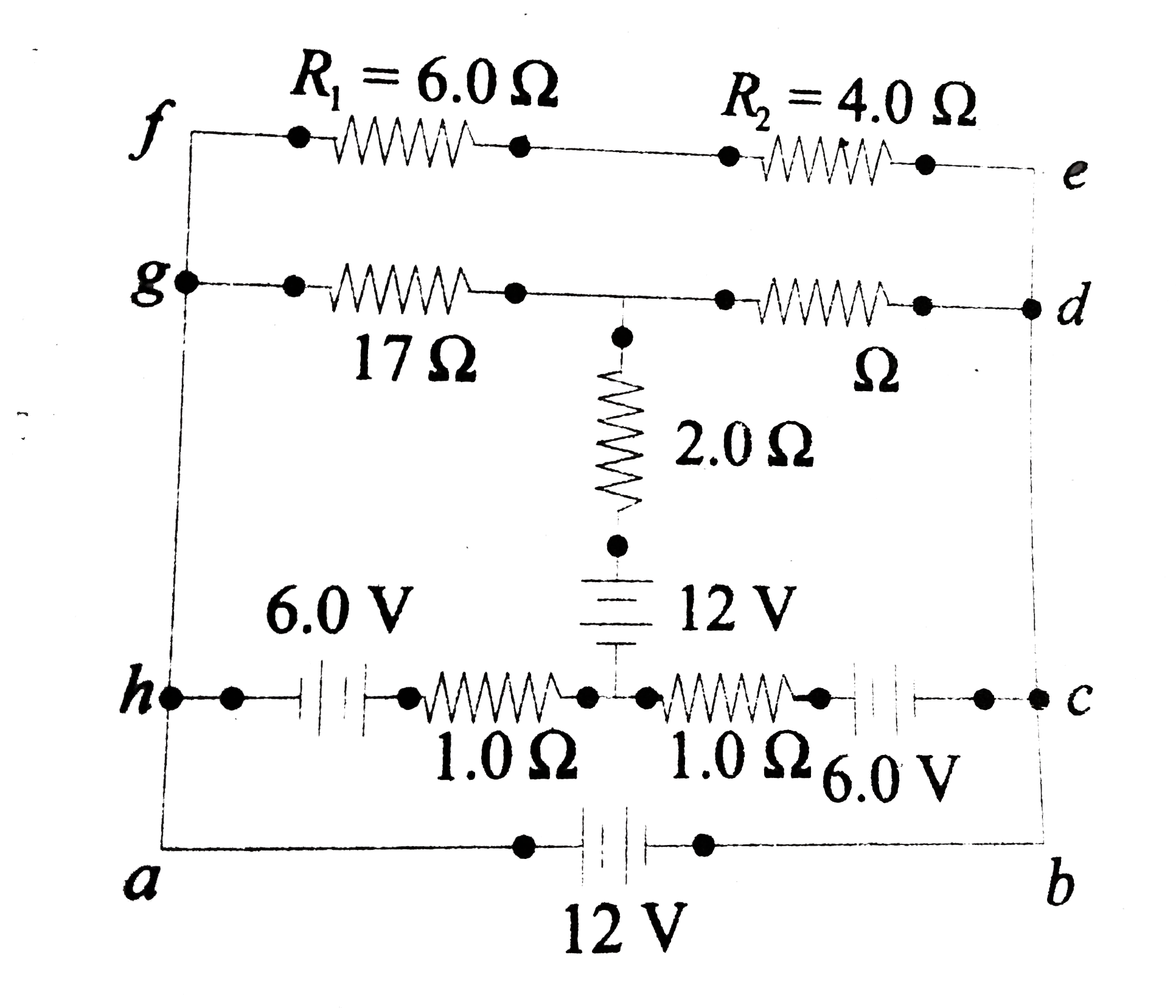
In the circuit shown in fig. mark the correct options.
 View Solution
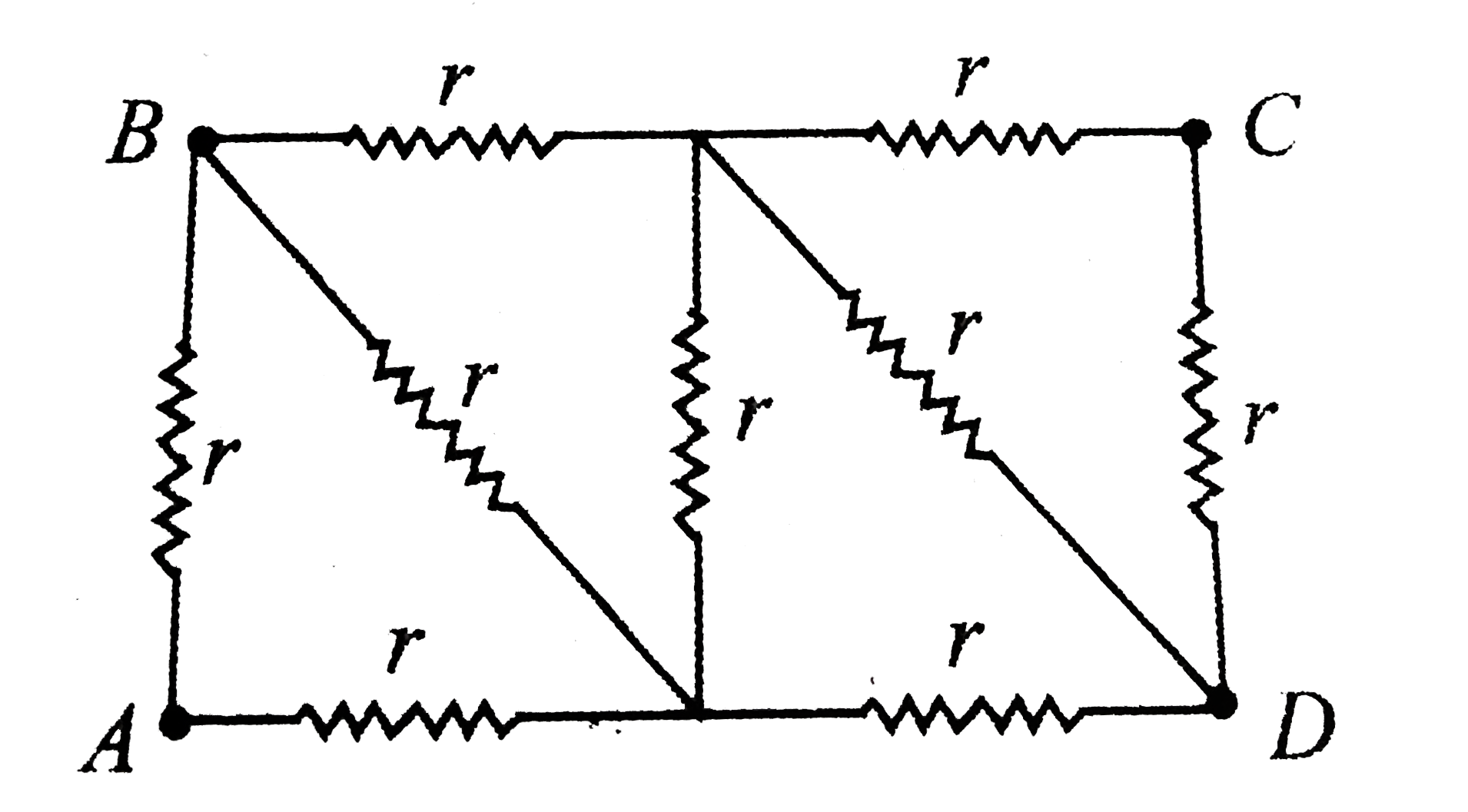
For the circuit shown in fig. the equivalent resistance between A and C is
 View Solution
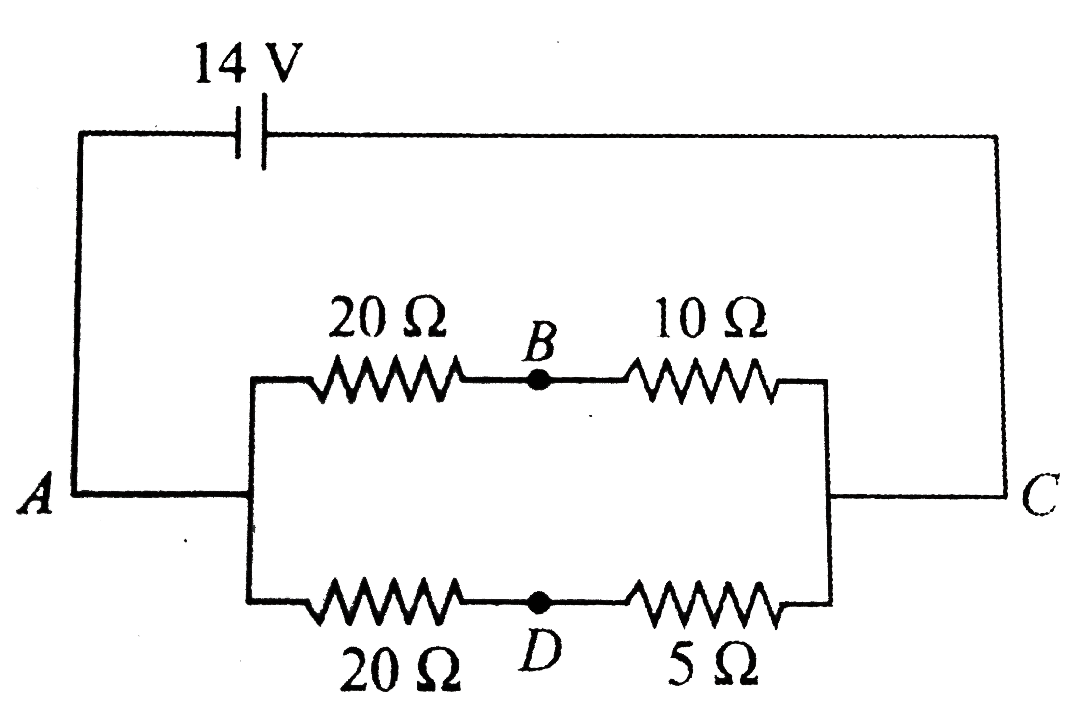
What resistor should be connected in parallel with the 20Ω resistor in branch ADC in the circuit shown in fig. so that potential difference between B and D may be zero ?
 View Solution
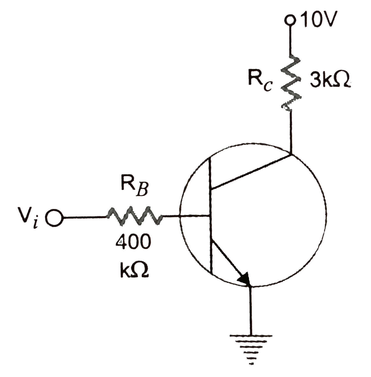
In the circuit shown in Fig. when the input voltage of the base resistance is 10V,Vbe is zero and Vce is also zero. Find the values of I,I and β.
 View Solution
In the given circuit (as shown in fig. 5.319).
 View Solution
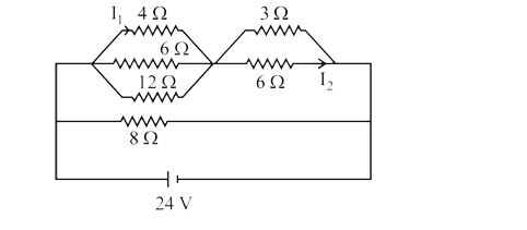
In the circuit shown in fig., the value of I1+I2 is
 View Solution

