In the given circuit values are as follows ε1=2V,ε2=4V,R1=1Ω and R2=R3=1Ω. Calcualte the Currents through R1,R2andR3.
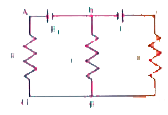
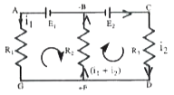
Let i1,i2 are currents across R1andR3.
(i1+i2) is current across R2.
Their direction are taken as shown
From Kirchoff.s second law for AGFBA loop
−i1R1−(i1+i2)R2+E1=0
i1+i1+i2=2⇒2i1+i2=2→(1)
From Kirchooff.s second law for BCDEB loop
−i2R3−(i1+i2)R2+E2=0
i2+i1+i2=⇒i2+2i2=4→(2)
Solving equation (1) and (2)
we get i1=0A,i2=2A
Thus currents across R1 is 0,
while across R3 and R_(2) are 2A each
Topper's Solved these Questions
- CURRENT ELECTRICITYBOOK - AAKASH SERIESCHAPTER - CURRENT ELECTRICITYEXERCISE - EXERCISE - IA
2 Videos
- CURRENT ELECTRICITYBOOK - AAKASH SERIESCHAPTER - CURRENT ELECTRICITYEXERCISE - ADDITIONAL PRACTICE EXERCISE (LEVEL -II PRACTICE SHEET (ADVANCED) (Linked Comprehension Type Questions))
9 Videos
- CURRENT ELECTRICITYBOOK - AAKASH SERIESCHAPTER - CURRENT ELECTRICITYEXERCISE - PROBLEMS (LEVEL-II)
27 Videos
- DUAL NATURE OF RADIATION AND MATTERBOOK - AAKASH SERIESCHAPTER - DUAL NATURE OF RADIATION AND MATTEREXERCISE - PRACTICE EXERCISEX
42 Videos
Similar Questions
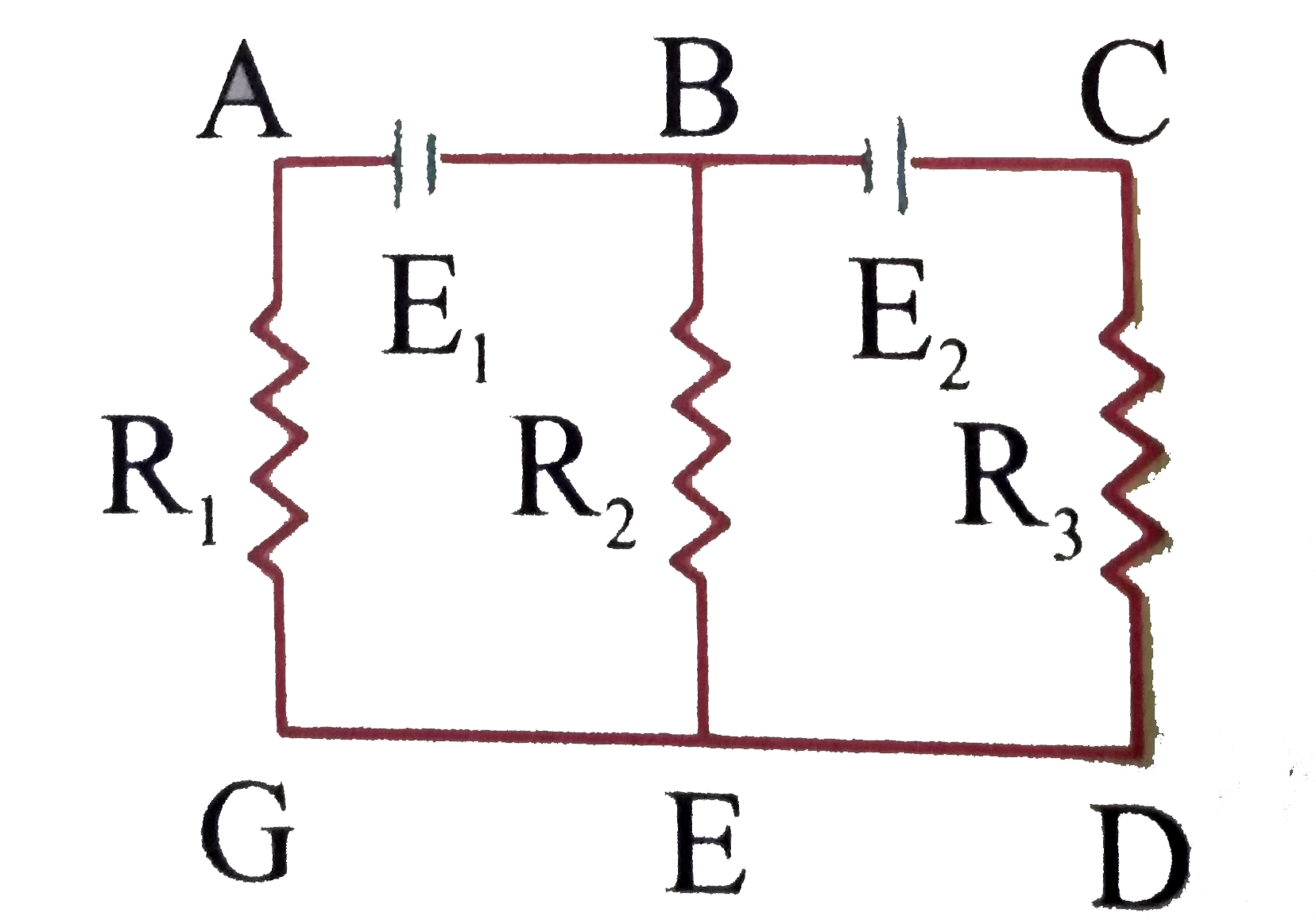
In the given circuit values are as follows
ε=2V,ε2=4V,R1=1Ω and R2=R3=1Ω.
Calculate the current through R1,R2 and R3
View SolutionIn the circuit shows in Fig E=15V, R1=1Ω, R2=1Ω, R3=2Ω, and L=1.5H. The currents flowing through R1,R2,and R3 are i1,i2, and i3, respectively.
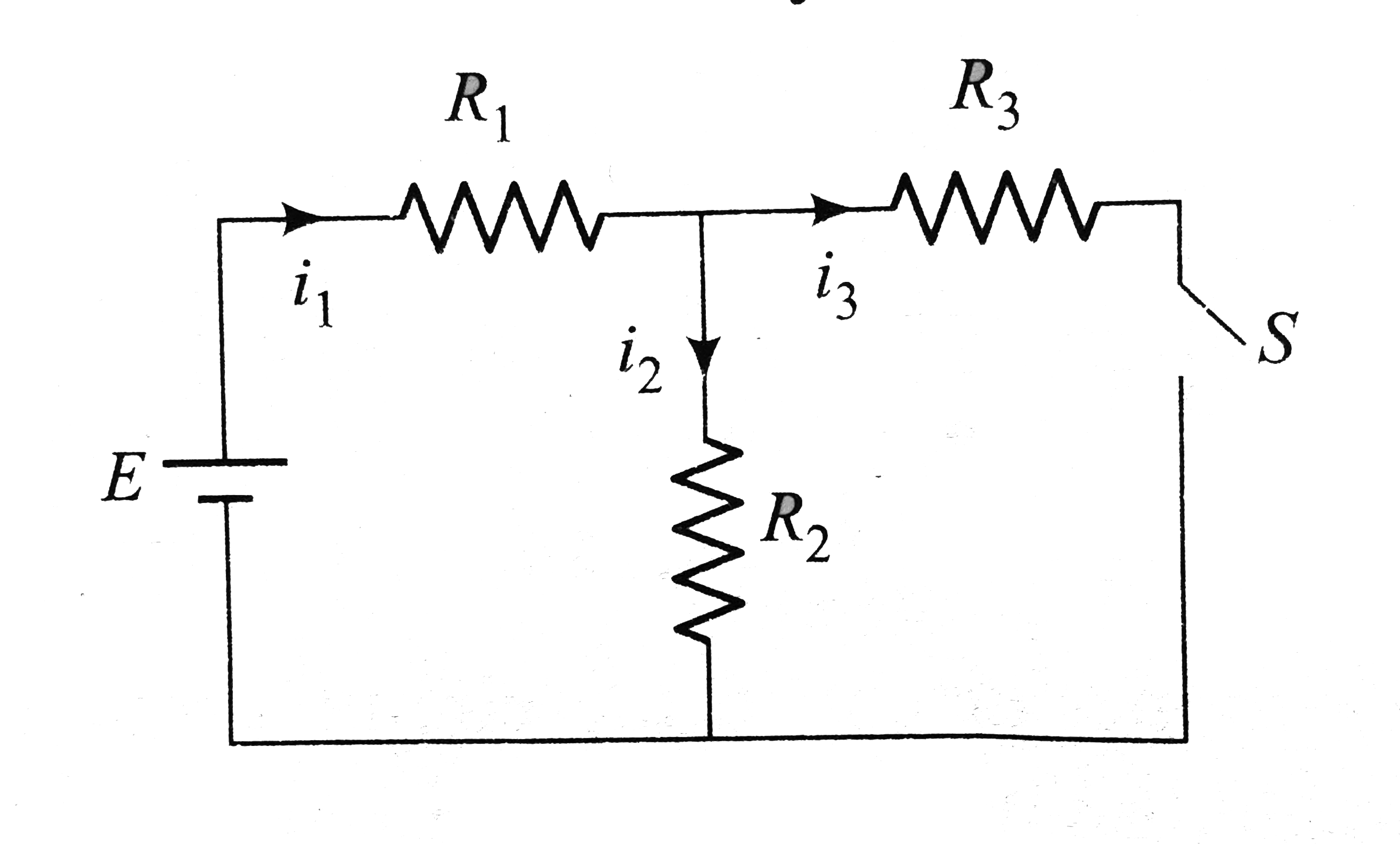
Immediately after connecting switch S,
View Solution
Knowledge Check
In the circuit shows in Fig E=15V, R1=1Ω, R2=1Ω, R3=2Ω, and L=1.5H. The currents flowing through R1,R2,and R3 are i1,i2, and i3, respectively.
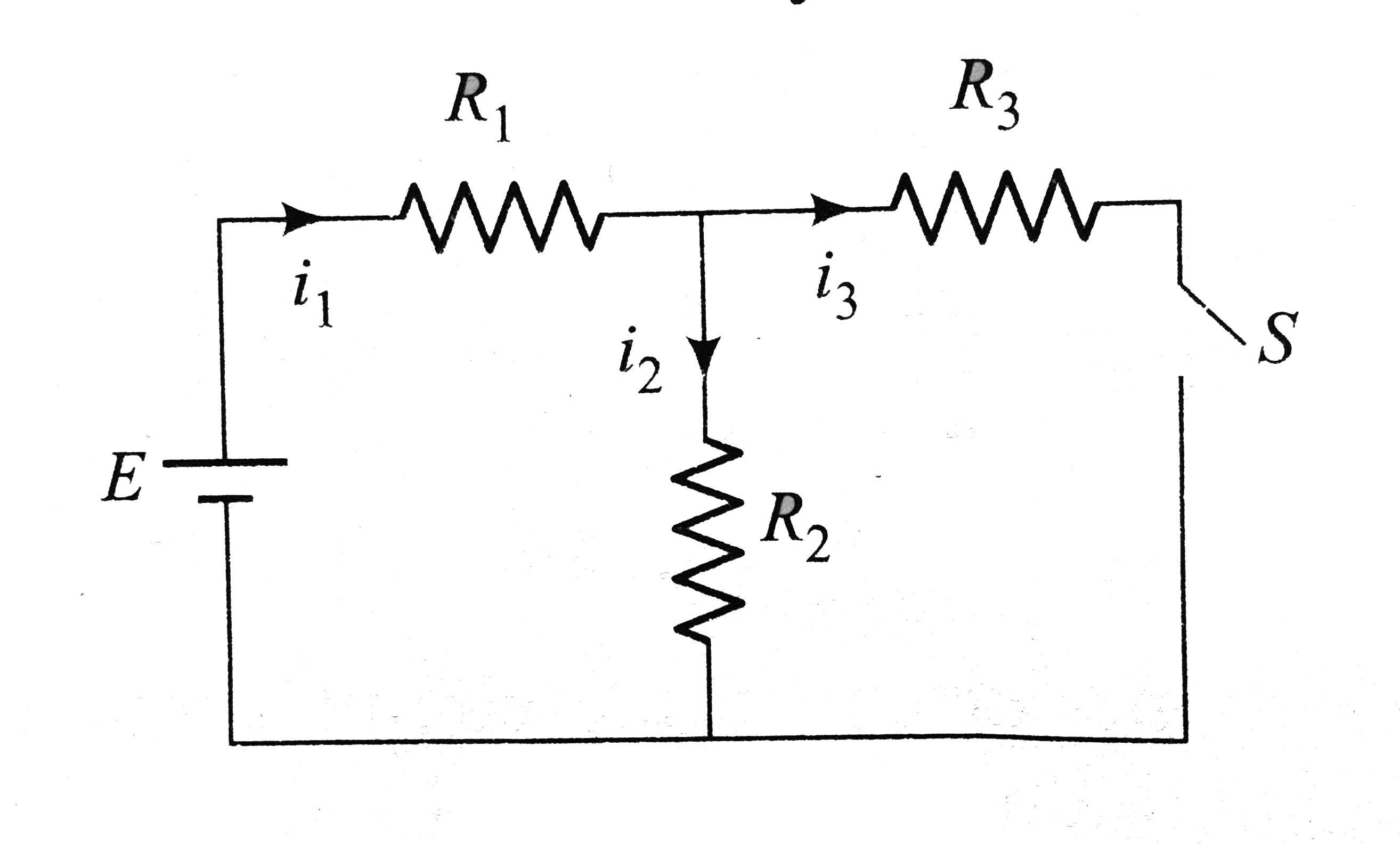
After the circuit reaches the steady state,Ai1=9A, i2=6A, i3=3ABi1=9A, i2=3A, i3=6ACi1=6A, i2=6A, i3=0ADi1=0A, i2=0A, i3=0AIn the circuit shows in Fig E=15V, R1=1Ω, R2=1Ω, R3=2Ω, and L=1.5H. The currents flowing through R1,R2,and R3 are i1,i2, and i3, respectively.
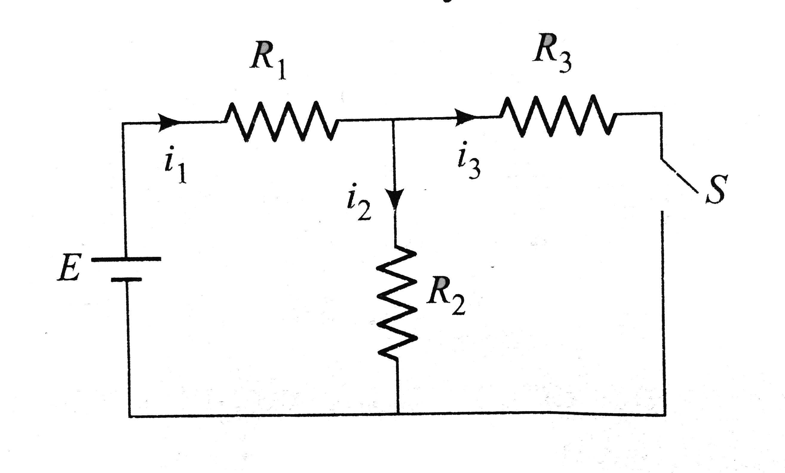
Immediately after tuning switch S on,Ai1=i2=7.5A, i3=0ABi1=i3=5A, i2=0ACi1=i2=9A, i3=0ADi1=i2=i3=0AIn the circuit shows in Fig E=15V, R1=1Ω, R2=1Ω, R3=2Ω, and L=1.5H. The currents flowing through R1,R2,and R3 are i1,i2, and i3, respectively.

Immediately after connecting switch S,Ai3=0A and di3dt=0As−1Bi3=0A and di3dt≠0As−1Ci3=0A and the rate at which magnetic energy stored is not zeroDNone of these
In the circuit shows in Fig E=15V, R1=1Ω, R2=1Ω, R3=2Ω, and L=1.5H. The currents flowing through R1,R2,and R3 are i1,i2, and i3, respectively.

Immediately after tuning switch S on,
View SolutionIn the circuit shown, E1=7V,E2=7V,R1=R2=1Ω and R3=3Ω respectively. The current through the resistance R3
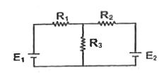
View SolutionIn the circuit shown, E1=7V,E2=7V,R1=R2=1Ω and R3=3Ω respectively. The current through the resistance R3

View SolutionIn the circuit shown, E1=7V,E2=7V,R1=R2=1Ω and R3=3Ω respectively. The current through the resistance R3

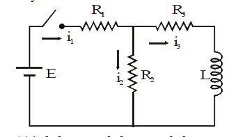
View SolutionIn the circuit shown in adjoining fig E =10V, R1=1ΩR2=2Ω,R3=3ΩandL=2H. Calculate the value of current i1,i2andi3 immidiately after key S is closed :-
View Solution
