In the L-C-R circuit as shown in figure,
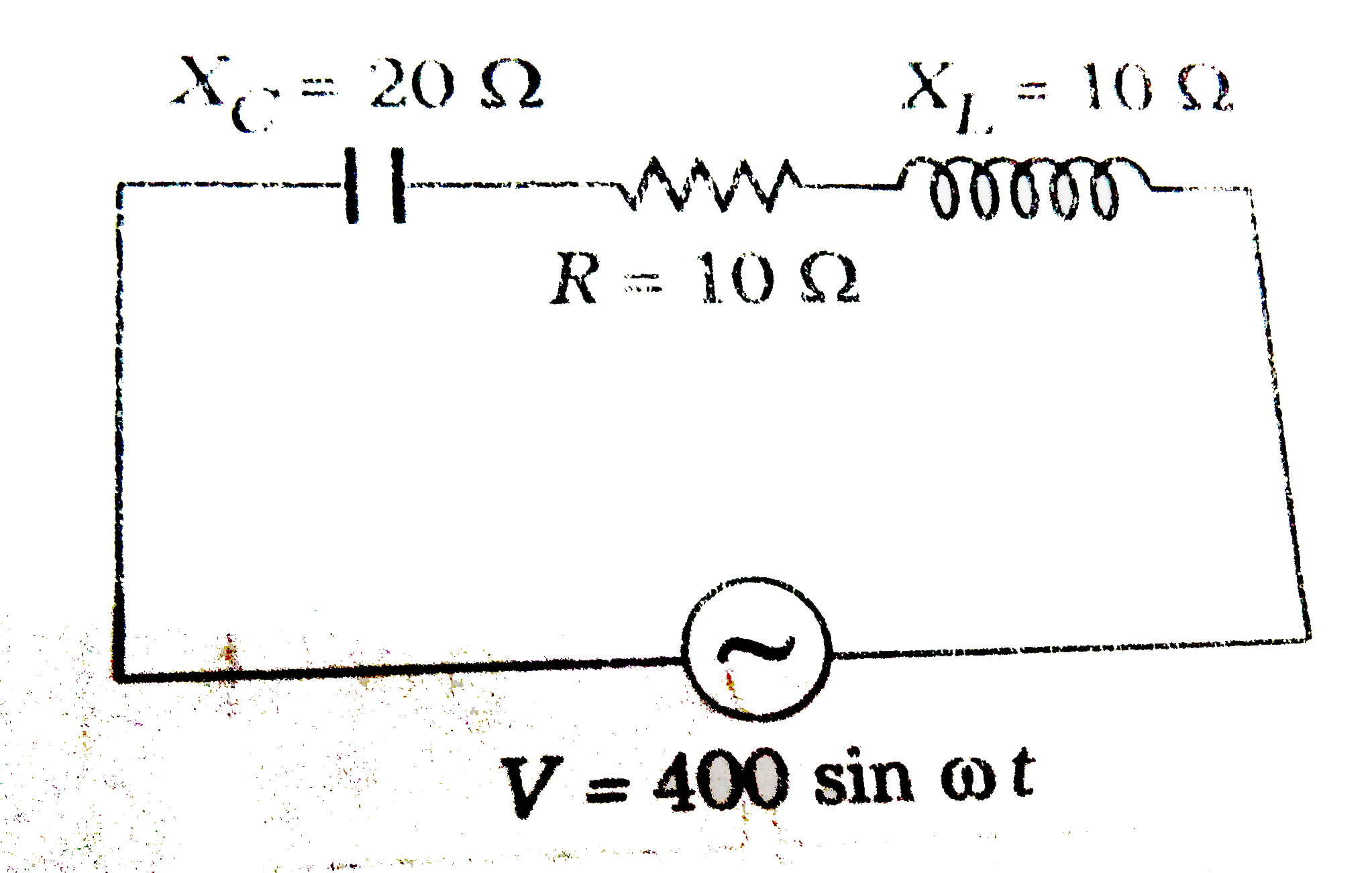
Current will lead the voltage
Rms value of current is 20 A
Power factor of the circuit is 1√2
Voltage drop across resistance is 200 V
The correct Answer is:A, B, C, D
(a,b,c,d) XC>XL, Hence, current will lead the voltate.
Z=√R2+(XC−XL)2=10√2Ω
∴Irms=VrmsZ=400√210√2=1√2
VR=IrmsR=(20)(1)=200V
Similar Questions
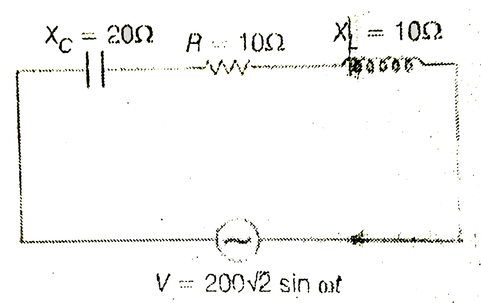
In LCR circuit as shown in figure
 View Solution
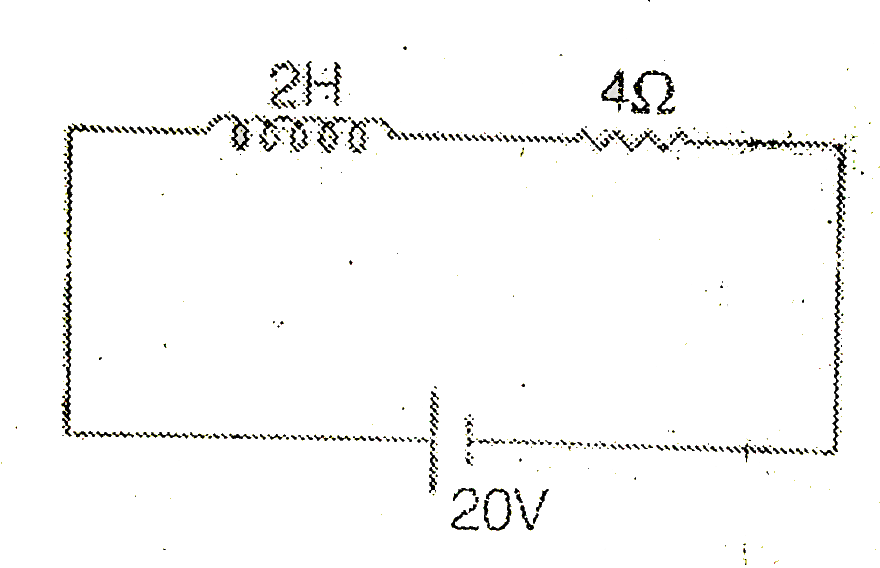
In the L-R circuit as shown in figure, potential difference across the resistance at some instant is 4 V. Then
 View Solution
The power dissipated in the resistance R, in the circuit as shown in the figure, is maximum if R is equal to
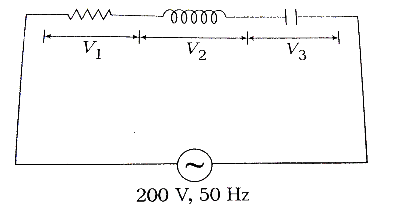
View SolutionFor series L-C-R circuit shown in the figure, the readings of V2 and V3 are same and each equal to 100 V .Then
 View Solution
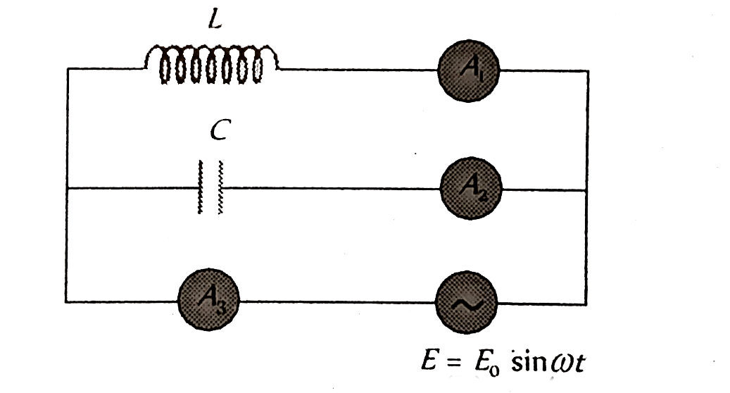
An inductor L and a capacitor C are connected in the circuit as shown in the figure. The frequency of the power supply is equal to the resonant frequency of the circuit. Which ammeter will read zero ampere
 View Solution
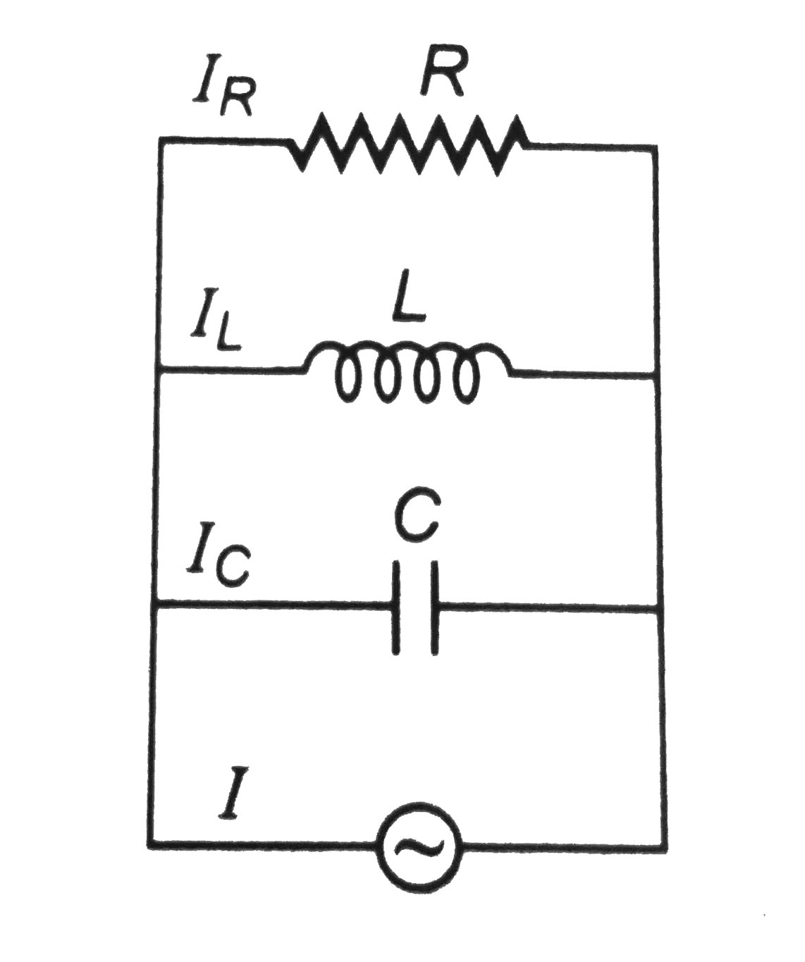
In a parallel L−C−R circuit as shown in figureure if IR,IL,IC and I represent the rms values of current flowing through resistor, capacitor and the source, then choose the appropriate correct answer.
 .View Solution
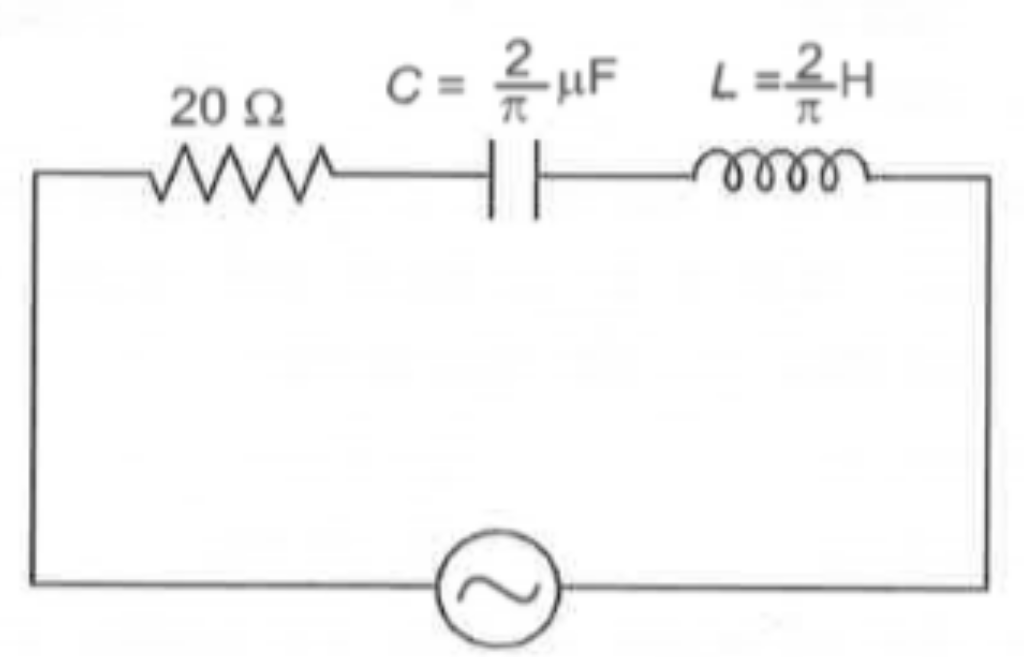
In an AC circuit as shown in the figure, the source is of r.m.s voltage 200 V and variable frequency. At resonance, the circuit
 View Solution
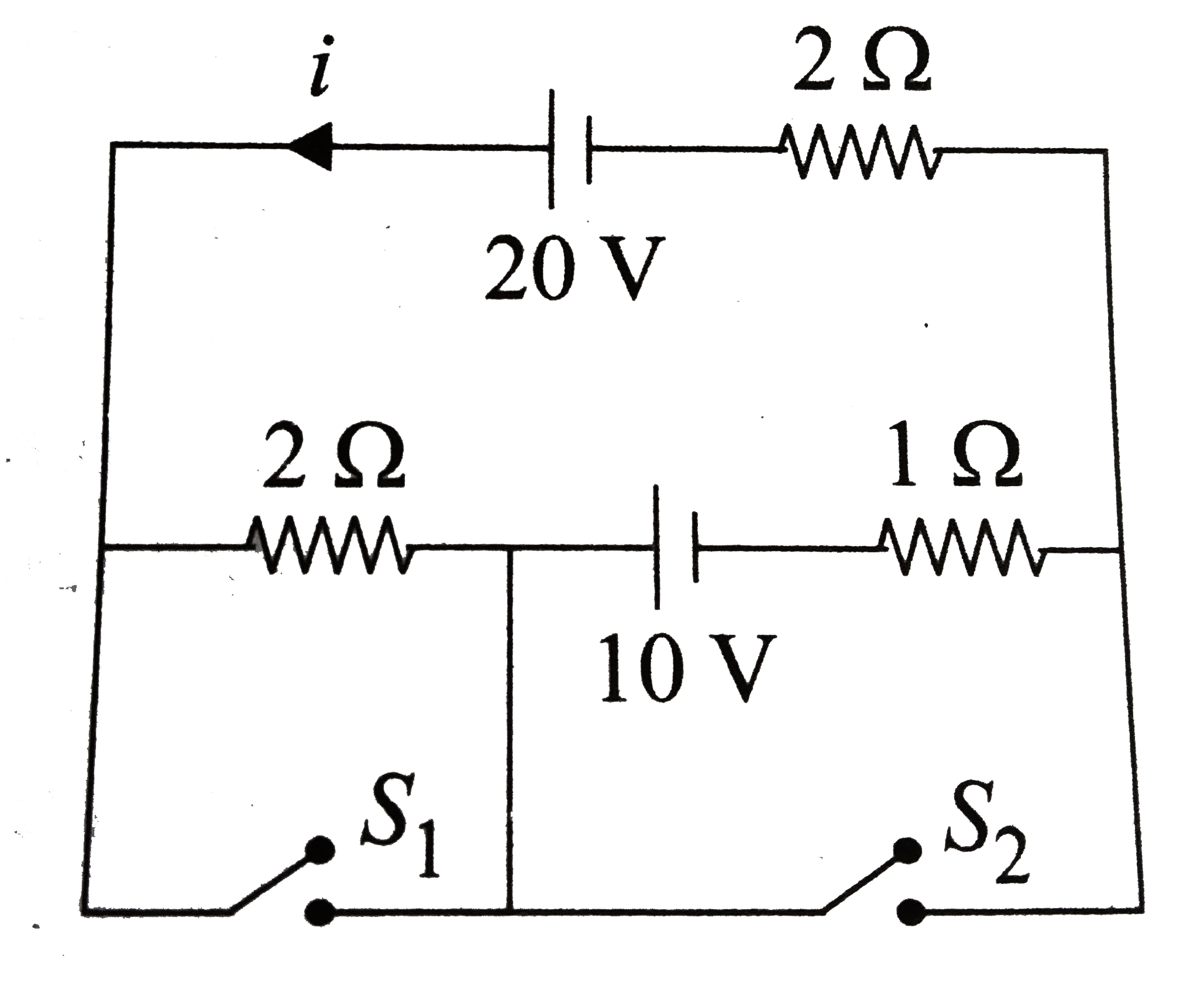
In the circuit shown in figure,
 View Solution
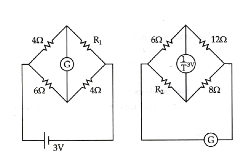
In the circuits shown in the figures, the galvanometers show no deflection. Find the ratio of R1 and R2.
 View Solution
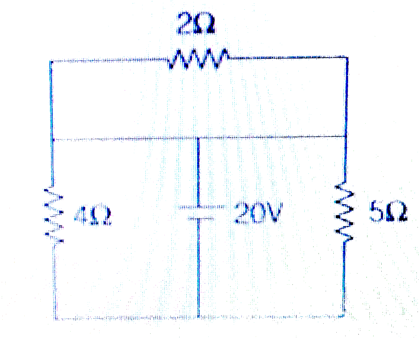
In the circuit shown in figure
 View Solution

