Initially two capacitors are charged to different potential differences as shown in figure and then connected in parallel as shown. Which of the following is incorrect about this circuit?
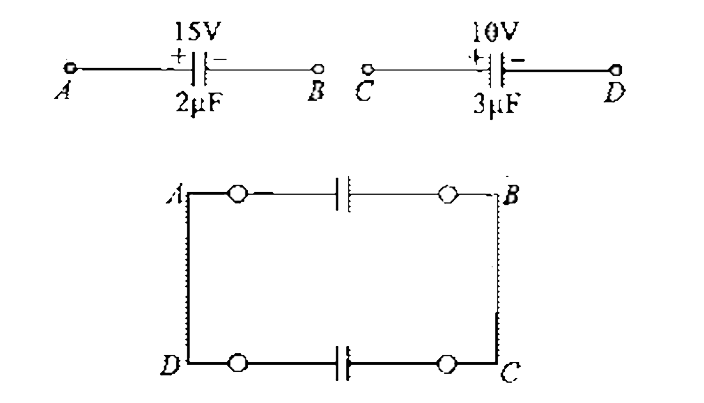
Final charge on each capacitor will be zero
Final total electrical energy of the capacitors will be zero
Total change from A to D is 30μC
Total charge flown from A to D is −30μC
The correct Answer is:D
Step by step video, text & image solution for Initially two capacitors are charged to different potential differences as shown in figure and then connected in parallel as shown. Which of the following is incorrect about this circuit? by Physics experts to help you in doubts & scoring excellent marks in Class 12 exams.
Topper's Solved these Questions
- BOOK - PHYSICS GALAXY - ASHISH ARORACHAPTER - CAPACITANCEEXERCISE - ADVANCE MCQS26videos
CAPACITANCE
- BOOK - PHYSICS GALAXY - ASHISH ARORACHAPTER - CAPACITANCEEXERCISE - UNSOLVED NUMERICAL PROBLEMS40videos
CAPACITANCE
- BOOK - PHYSICS GALAXY - ASHISH ARORACHAPTER - CAPACITANCEEXERCISE - CONCEPTUAL MCQA32videos
CAPACITANCE
- BOOK - PHYSICS GALAXY - ASHISH ARORACHAPTER - ATOMIC PHYSICSEXERCISE - Unsolved Numerical Problems39videos
ATOMIC PHYSICS
- BOOK - PHYSICS GALAXY - ASHISH ARORACHAPTER - CURRENT ELECTRICITYEXERCISE - All Questions389videos
CURRENT ELECTRICITY
Similar Questions
Knowledge Check
- Question 1 - Select One
In, the initial status of capacitors and their connections is show. Which of the folllowin is incorrect about this circuit?
 .AFinal charge on each capacitor will be zero.BFinal total electrical energy of the cpacitor will be zero.CTotal charge flowing from A to D is 30μC,DTotal charge flowing from A to D is 60μC,
 - Question 2 - Select One or More
When two identical capacitors are charged individually to different potentials & then connected in parallel, after disconnecting from the source then
ANet potential difference across them is equal to sum of individual potential differencesBNet potential difference across them is not equal to sum of · individual initial potential diflerencesCNet energy stored in the two capacitors is less than the sum of individual initial energiesDNone of these - Question 3 - Select One
The potential difference between A and B in the circuit shown is -
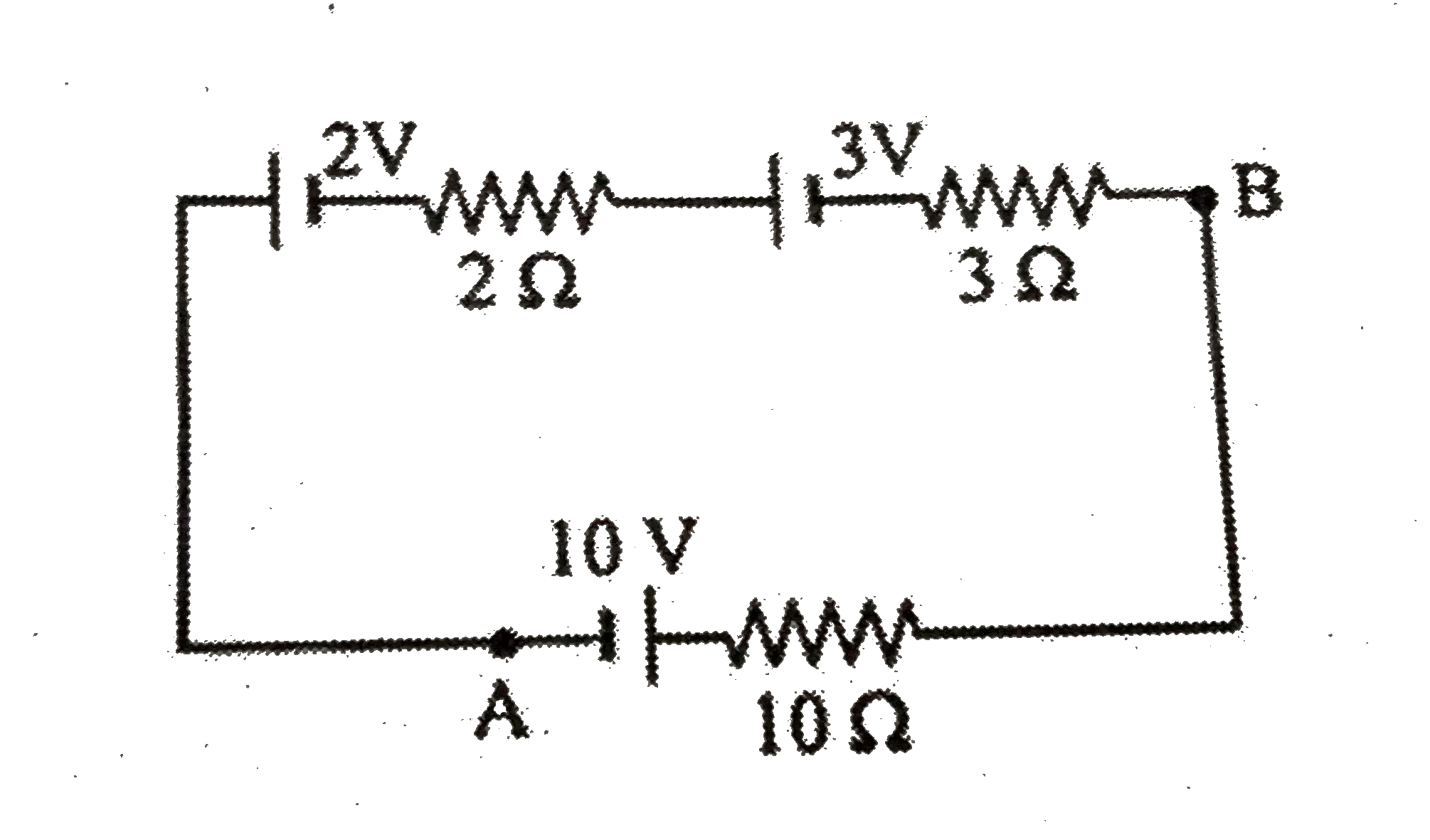 A10VB5 VC15 VDzero
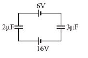
What is the potential difference across 2μF capacitor in the circuit shown?
 View Solution
What is the potential difference across 2μF capacitor in the circuit shown?
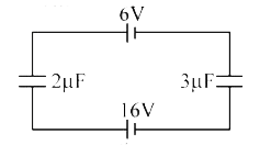 View Solution
The potential difference between points a and b of circuits shown in figure is
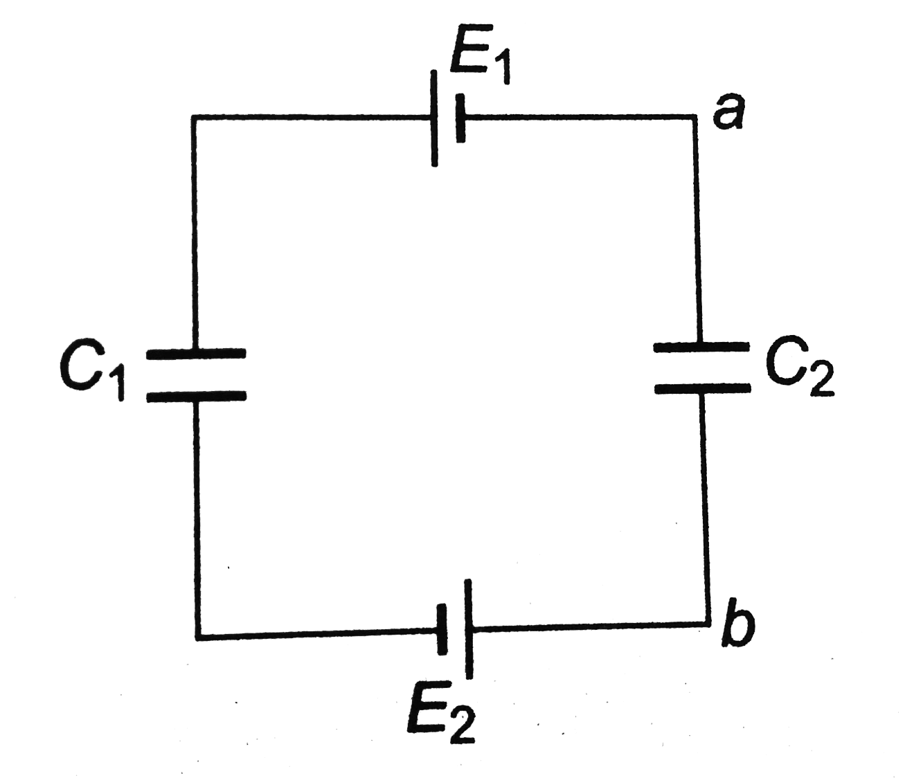 View Solution
Six identical capacitors are joined in parallel, charged to a potential difference of 10 V, separated and then connected in series. Then the potential difference between the free plates is
View SolutionThe potential difference between points A and B in the circuit shown in figure will be
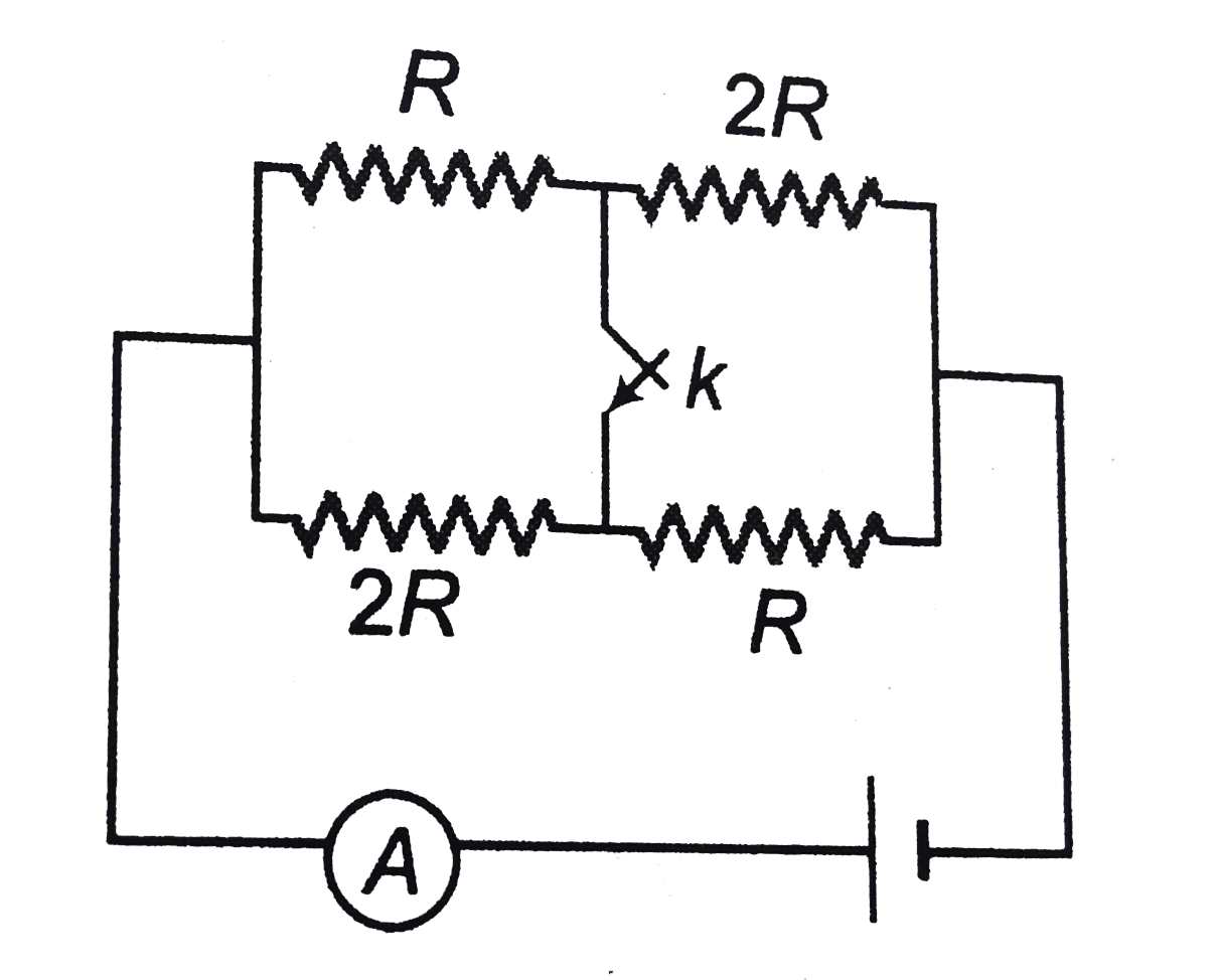 View Solution


