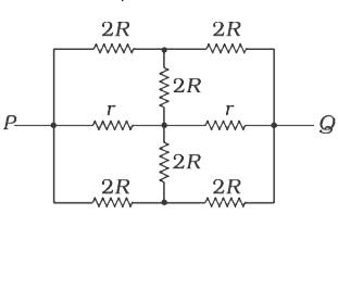
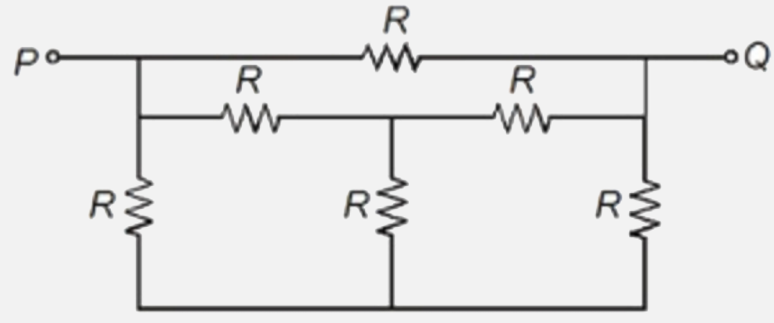
The effective capacitance between the points P and Q of the arrangement shown in the figure is
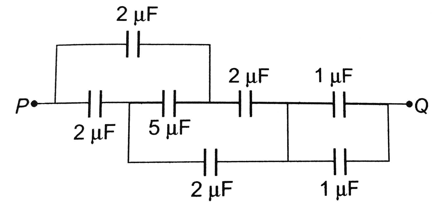
A
12μF
B
1μF
C
2μF
D
1.33μF
Video Solution
Text Solution
The correct Answer is:B
|
Answer
Step by step video, text & image solution for The effective capacitance between the points P and Q of the arrangement shown in the figure is by Physics experts to help you in doubts & scoring excellent marks in Class 12 exams.
Updated on:21/07/2023Topper's Solved these Questions
- CAPACITANCEBOOK - PHYSICS GALAXY - ASHISH ARORACHAPTER - CAPACITANCEEXERCISE - ADVANCE MCQS
26 Videos
- CAPACITANCEBOOK - PHYSICS GALAXY - ASHISH ARORACHAPTER - CAPACITANCEEXERCISE - UNSOLVED NUMERICAL PROBLEMS
40 Videos
- CAPACITANCEBOOK - PHYSICS GALAXY - ASHISH ARORACHAPTER - CAPACITANCEEXERCISE - CONCEPTUAL MCQA
32 Videos
- ATOMIC PHYSICSBOOK - PHYSICS GALAXY - ASHISH ARORACHAPTER - ATOMIC PHYSICSEXERCISE - Unsolved Numerical Problems
39 Videos
- CURRENT ELECTRICITYBOOK - PHYSICS GALAXY - ASHISH ARORACHAPTER - CURRENT ELECTRICITYEXERCISE - All Questions
389 Videos
Similar Questions
Knowledge Check
The effective capacitance between the point P and Q in the given figure is.
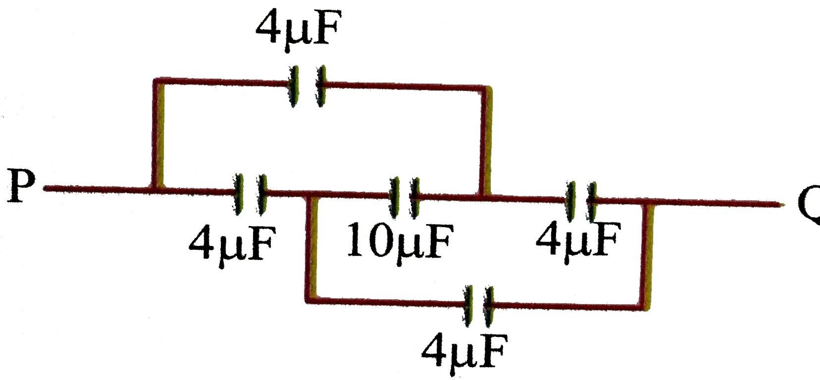 .A4μFB16μFC26μFD10μF
What is the effective capacitance between points X and Y ?
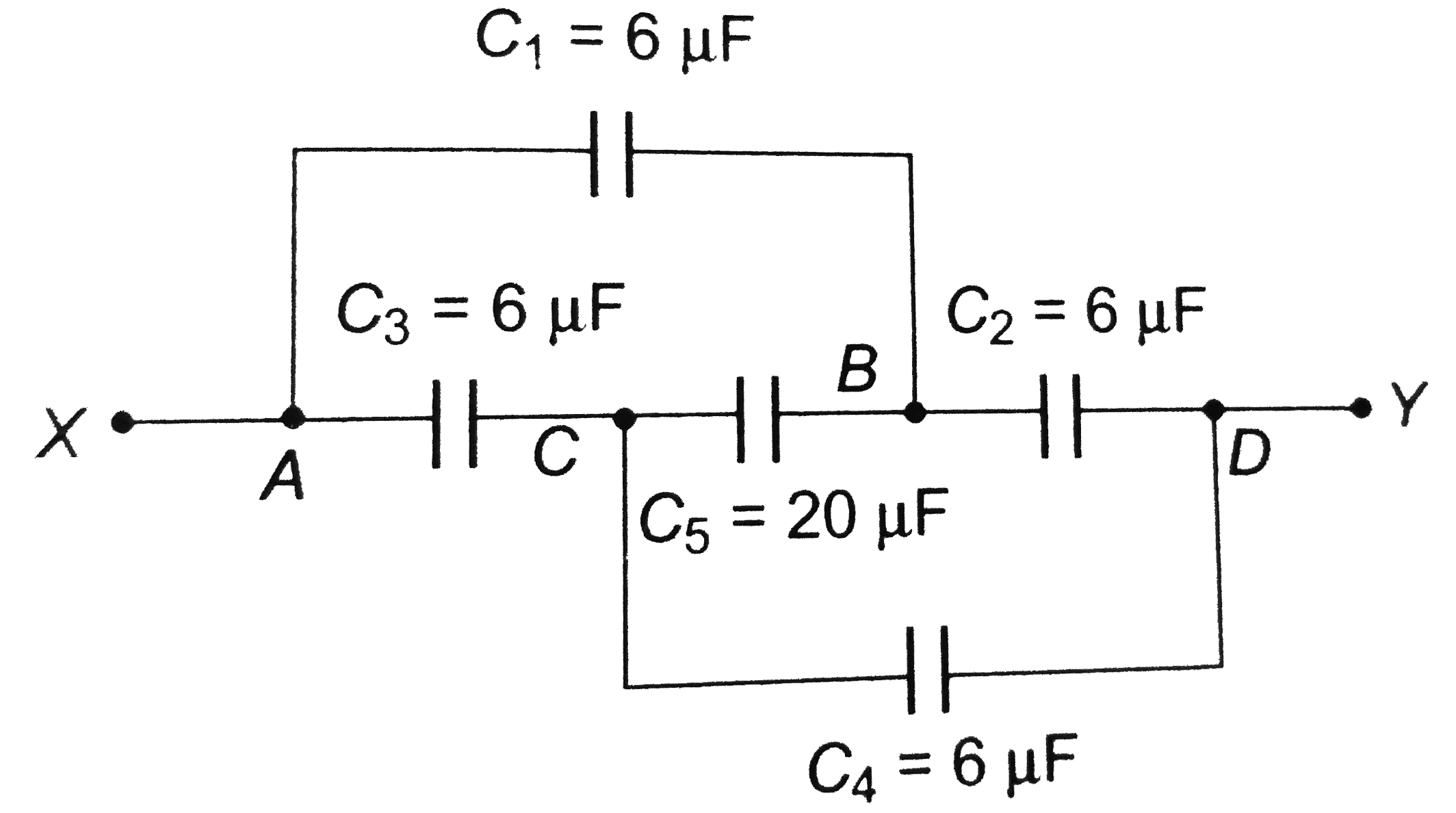 A24μFB18μFC12μFD6μF
What is the effective capacitance between points X and Y ?
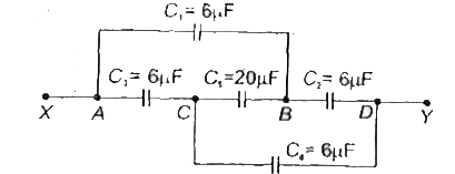 A12 μFB19 μFC24 μFD6 μF
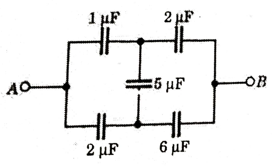
find the capacitance between the points A and B of the assembly shown in figure.
View SolutionThe effective capacitance between points and Y of figure shown is
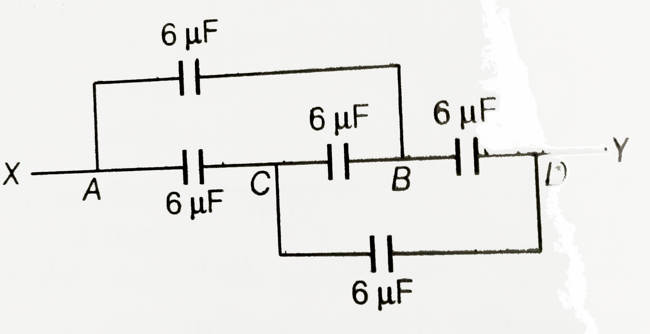
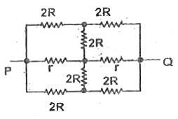
View SolutionThe effective resistance between points P and Q of the electrical circuit shown in the figure is
View SolutionThe equivalent capacitance between points P and Q of the combination shown in figure is

View SolutionFind the effective capacitance between A and B of the arrangement shown ?
View Solution

