Materials: connecting wires, electric cells, electrical resistance, voltmeter, ammeter, plug key.
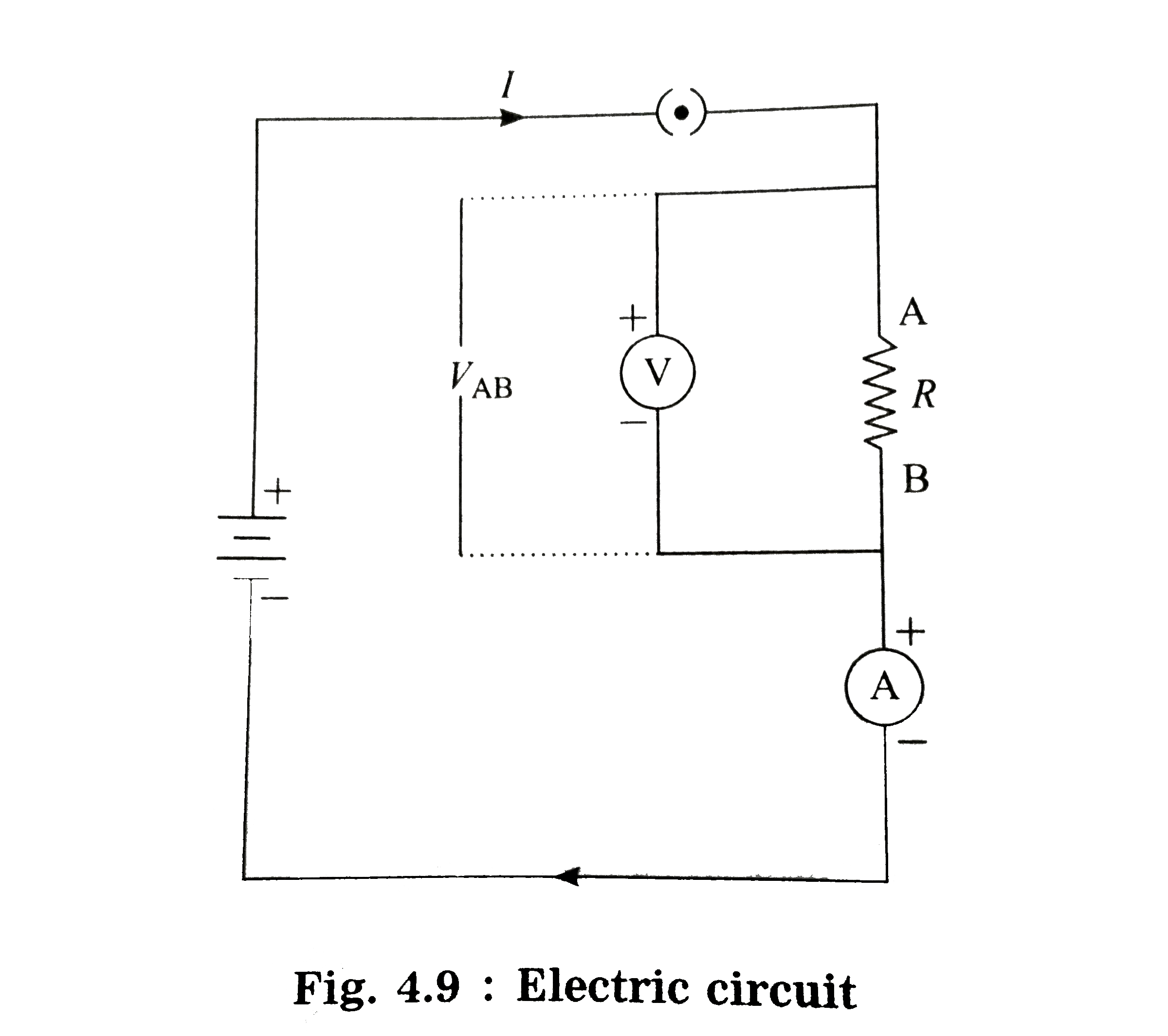
Procedure: Connect the circuit as shown in the figure below, after taking the components with proper values.
What hapeens to the energy provided by the cell?

The energy provided by the cell is received by the resistor and is converted into heat energy. Hence, the temperature of the resistor is increased.
Topper's Solved these Questions
- EFFECTS OF ELECTRIC CURRENT BOOK - TARGET PUBLICATIONCHAPTER - EFFECTS OF ELECTRIC CURRENT EXERCISE - Chapter Assesment
31 Videos
- EFFECTS OF ELECTRIC CURRENT BOOK - TARGET PUBLICATIONCHAPTER - EFFECTS OF ELECTRIC CURRENT EXERCISE - Solve the following problems
26 Videos
- EFFECTS OF ELECTRIC CURRENT BOOK - TARGET PUBLICATIONCHAPTER - EFFECTS OF ELECTRIC CURRENT EXERCISE - Practice Problems
24 Videos
- DISASTER MANAGEMENTBOOK - TARGET PUBLICATIONCHAPTER - DISASTER MANAGEMENTEXERCISE - CHAPTER ASSESSMENT
2 Videos
- ENVIRONMENTAL MANAGEMENT BOOK - TARGET PUBLICATIONCHAPTER - ENVIRONMENTAL MANAGEMENT EXERCISE - APPLY OUR KNOWLEDGE
28 Videos
Similar Questions
Material : Connecting wires , electric cells, electrical resistance, voltmeter , ammeter , plug key.
Procedure : Connect the circuit as shown in the accompanying figure after taking the components with proper values. Measure the current (I). Also measure the potential difference (V)AB between the two ends (A and B) of the resistance .
The potential at A is higher than the potential at B as the point A is connected to the positive electrode of the cell and the point B to the negative electrode of the cell.
What happens to this energy?
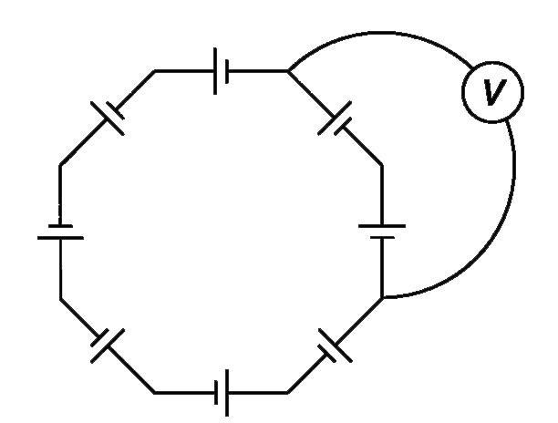
View SolutionEight identical 1 volt cells are connected to make a ring as shown in the figure. An ideal voltmeter is connected as shown. What will be its reading ?
View Solution
Knowledge Check
The current following through a resistor connected in an electric circuit and the potential difference applied across its ends are shown in the figures below :
The value of the resistance of the resistor is :
 A10ΩB15ΩC20ΩD25Ω
In measuring the values of resistance, different students connect ammeter and voltmeter as shown in following figures. Which of these will be correct?
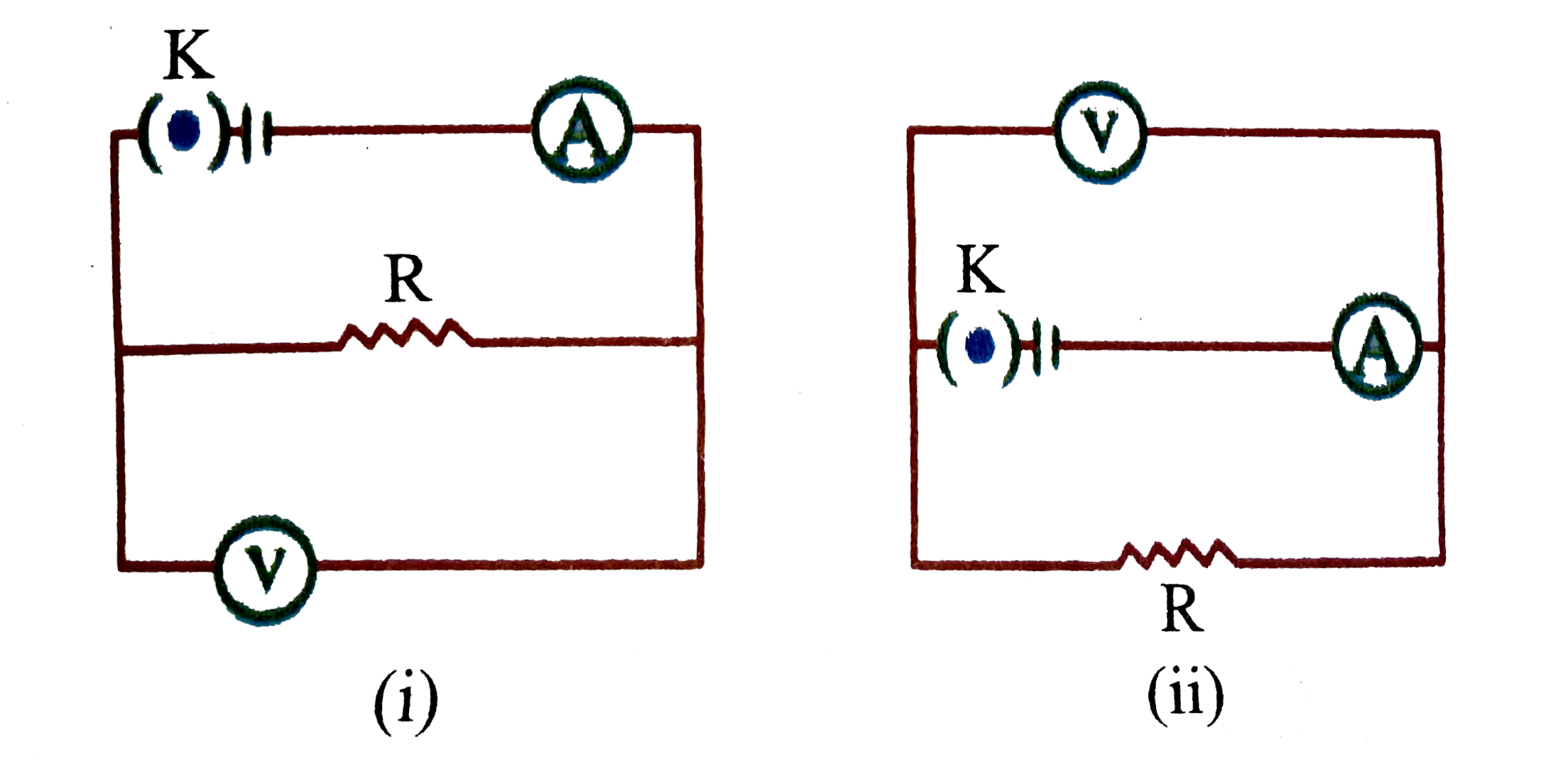 ABoth figures are correctBBoth are wrongCOnly figure (i) is correctDOnly figure (ii) is correct
The diagram in Fig. shows a cell of e.m.f. ε=2 volt and internal resistance r = 1 ohm connected to an external resistance R = 4 ohm. The ammeter A measures the current in the circuit and the voltmeter V measures the terminal voltage across the cell. What will be the readings of the ammeter and voltmeter when
the key K is closed.

View SolutionThe diagram in Fig. shows a cell of e.m.f. ε=2 volt and internal resistance r = 1 ohm connected to an external resistance R = 4 ohm. The ammeter A measures the current in the circuit and the voltmeter V measures the terminal voltage across the cell. What will be the readings of the ammeter and voltmeter when
the key K is open

View SolutionA voltmeter is connected in parallel with a variable resistance R which is in series with an ammeter and a cell as shown in the figure . For one value of R=2Ω,the reading are 0.25A and 1.0 V. What is the internal resistance of the cell ?

View SolutionConnect the circuit as shown in figure Connect a copper wire, thicker and straight as compared to the connecting wires, between A and B. Keep a magnetic needle adjacent to the wire. Keep the plug key open in the circuit and observe the direction of the needle. Close the plug key and observe the direction of the needle. What do you notice? Now interchange the connecting wires connected to the cell and observe the direction of the magnetic needle. Do you notice any relation between the direction of current and position of the needle?
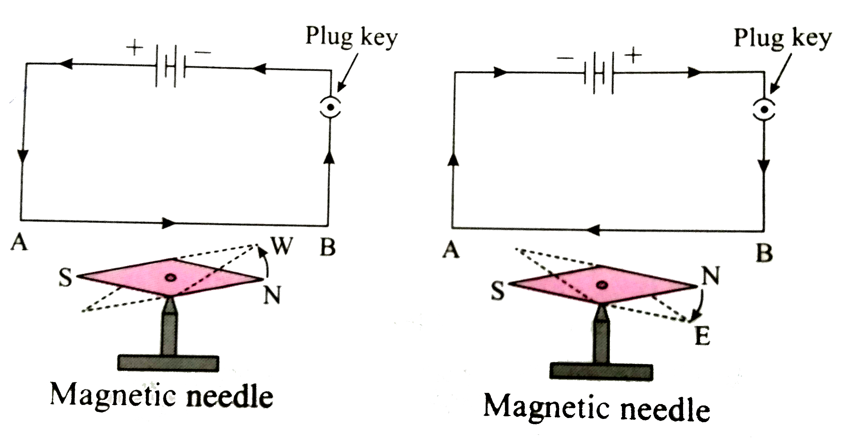
What do you learn from this experiment?
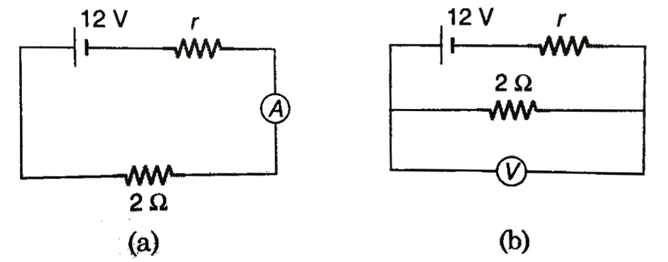
View SolutionA galvanometer (coil resistance 99Ω.) is converted into an ammeter using a shunt of 1Ω and connected as shown in figure (a). The ammeter reads 3A. The same galvanometer is convened into a voltmeter by connecting a resistance of 101Ω in series. This voltmeter is connected at, shown in figure (b). Its reading is found to be 45 of the full scale reading. Find :
(a) internal resistance r of the cell
(b) range of the ammeter and voltmeter
(c) full scale deflection current of the galvanometer.

View Solution
