Resistances of 6Ω each are connected in the manner shown in the following figure. The potential difference Vp−Vq is

13.6V
6V
3V
17.2V
The correct Answer is:C
From figure, effective resistance of network is ,
R=2+4=6Ω
Thus, VP−VQ=IR=0.5×6=3V
Topper's Solved these Questions
- BOOK - NIKITA PUBLICATIONCHAPTER - CURRENT ELECTRICITYEXERCISE - Multiple Choice Questions314videos
CURRENT ELECTRICITY
- BOOK - NIKITA PUBLICATIONCHAPTER - COMMUNICATION SYSTEMSEXERCISE - Multiple Choice Questions (Examples for Practice)8videos
COMMUNICATION SYSTEMS
- BOOK - NIKITA PUBLICATIONCHAPTER - ELASTICITYEXERCISE - MCQ314videos
ELASTICITY
Similar Questions
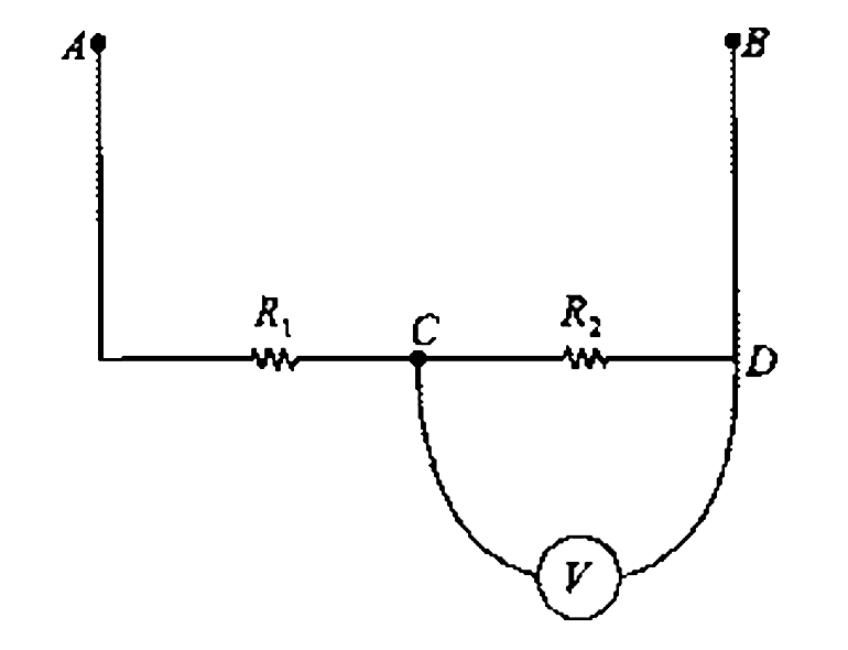
Resistances R1andR2, each 600Ω, are connected in series as shown in figure-3.382. The potential difference between points A and B is 120 V. Find the reading of voltmeter connected between points C and D ifits resistance is 120Ω
 View Solution
‘A point charge +Q is placed at point O as shown in the figure. Is the potential difference VA–VB positive.
 View Solution
Knowledge Check
- Question 1 - Select One
Resistances of 6 ohm each are connected in the manner shown in adjoining figure. With the current 0.5 ampere as shown in figure, the potential difference VP−VQ is
 A3.6VB6.0VC3.0VD7.2V
 - Question 2 - Select One
Six resistance are connected as shown in figure. If total current flowing is 0.5A, then the potrential difference VA−VB is
 A8 VB6 VC2 VD4 V
 - Question 3 - Select One
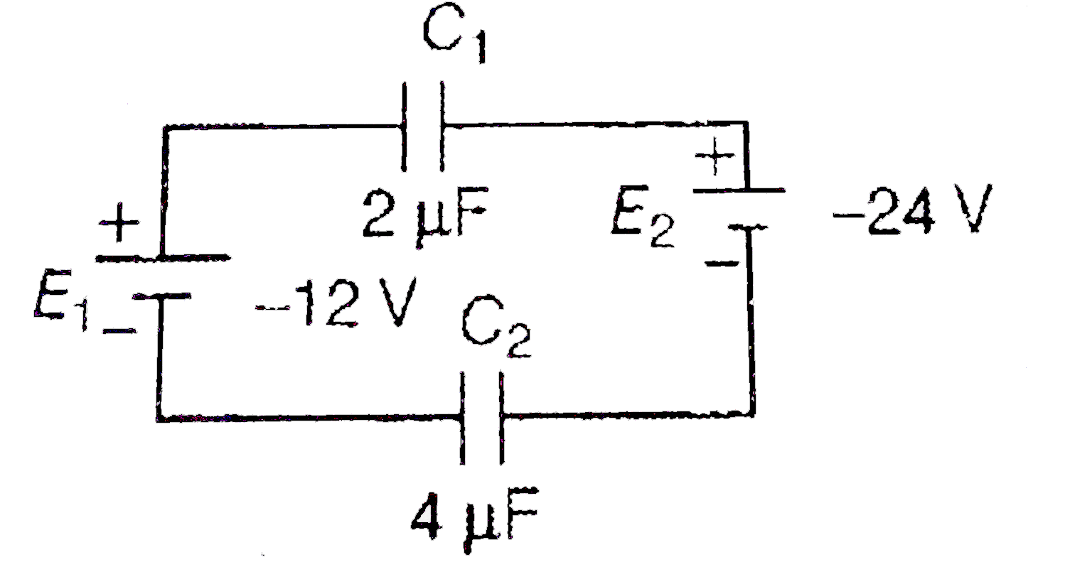
Two capacitors C1 and C2 are connected in a circuit as shown in figure. The potential difference (VA−VB) is
 A8VB−8VC12VD12V
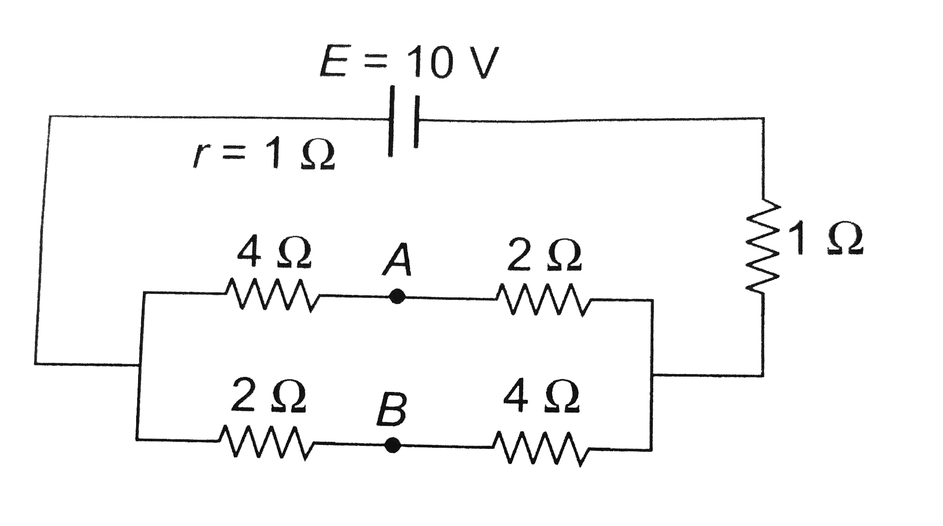
In the circuit shown below, the cell has an e.m.f. of 10V and internal resistance of 1ohm. The other resistances are shown in the figure. The potential difference VA−VB is
 View Solution
Resistances of 6 ohm each are connected in the manner shown in adjoining figure. With the current 0.5 ampere as shown in figure, the potential difference VP−VQ is
 View Solution
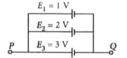
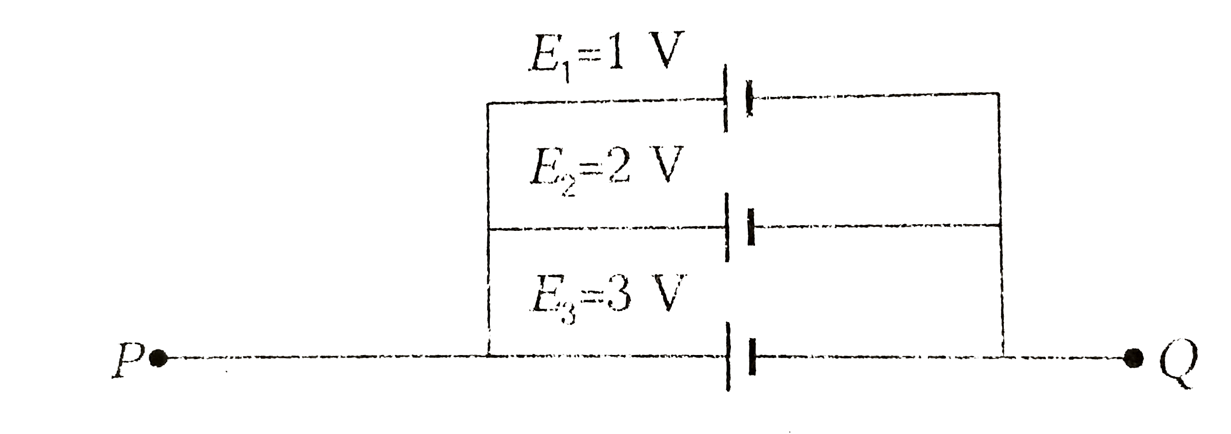
A circuit consists of three batteries of emf E1 = 1 V, E2=2VandE3=3V and internal resistances 1Ω,2Ωand1Ω respectively which are connected in parallel as shown in the figure. The potential difference between points P and Q is
 View Solution
A circuit consists of three batteries of emf E1=1V,E2=2V and E3=3V and internal resistance 1Ω,2Ω and 1Ω respectively which are connected in parallel as shown in figure. The potential difference between points P and Q is
 View Solution
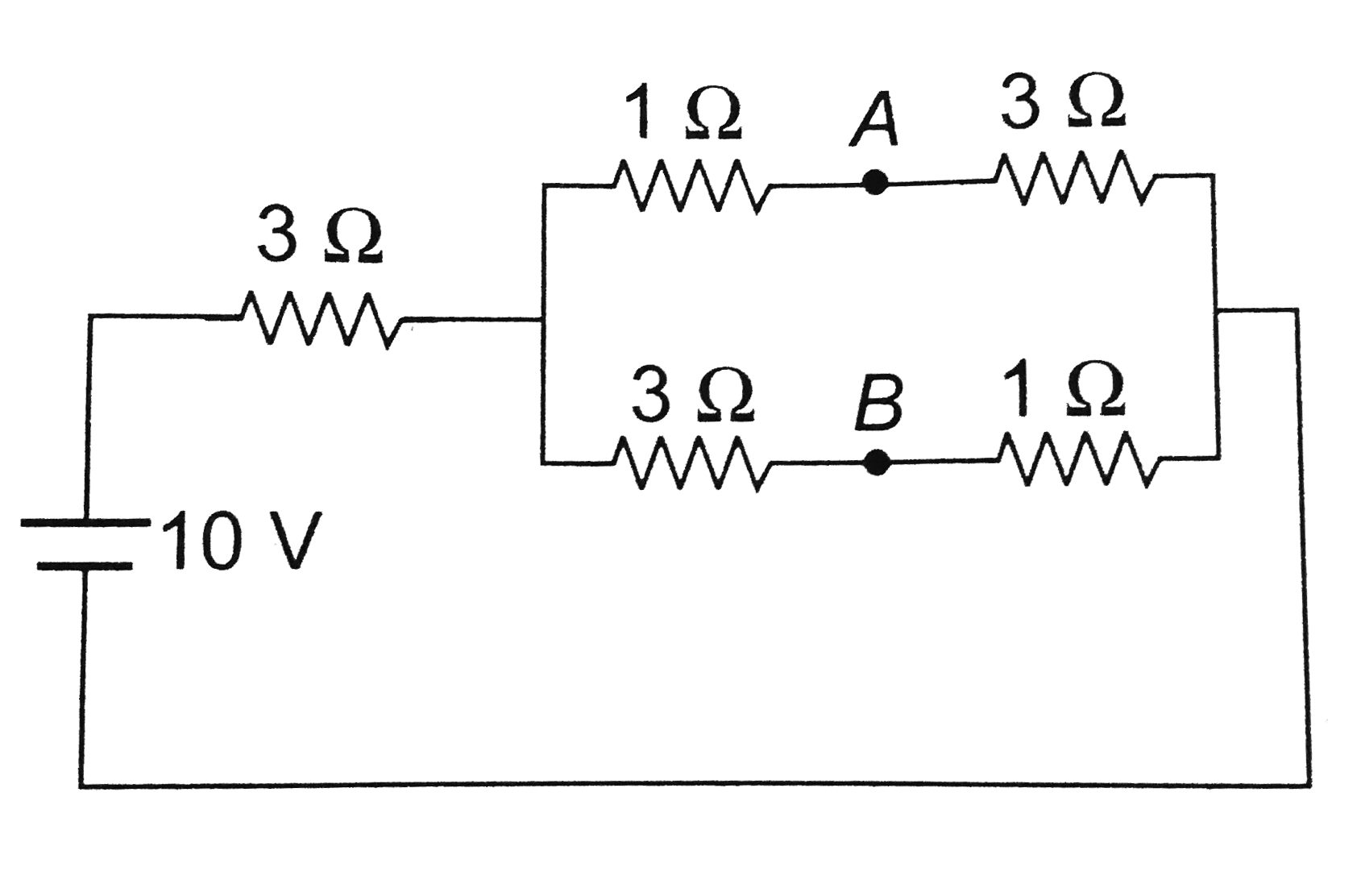
A battery of e.m.f. 10V is connected to resistance as shown in figure. The potential difference VA−VB between the point A and B is
 View Solution

