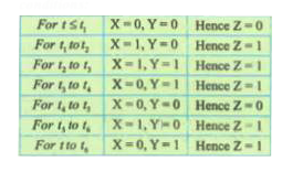
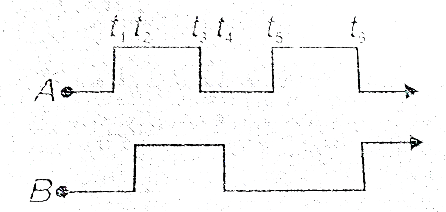
Sketch the output y from a NOR gate having input A and B as given in Fig.
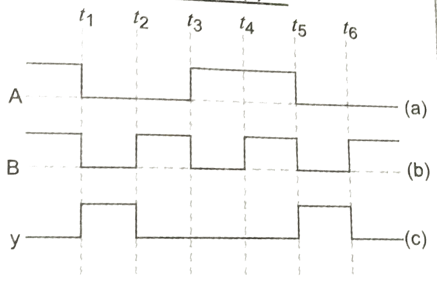
For NOR gate the Boolean expression is
¯¯¯¯¯¯¯¯¯¯¯A+B=y
For the given wave form, we have the following value for A, B and y.
For time t<t1,A=1,B=1 hencey =0
For time t1tot2,A=0,B=0 hencey =1
For time t2tot3,A=0,B=1 hencey =0
For time t3tot4,A=1,B=0 hencey =0
For time t4tot5,A=1,B=1 hencey =0
For time t5tot6,A=0,B=0 hencey =1
For time t>t6,A=0,B=1 hencey =0
The wave from for output y is as shown in Fig.
Topper's Solved these Questions
- ELECTRONIC DEVICESBOOK - PRADEEPCHAPTER - ELECTRONIC DEVICESEXERCISE - SAMPLE PROBLEM
2 Videos
- ELECTRONIC DEVICESBOOK - PRADEEPCHAPTER - ELECTRONIC DEVICESEXERCISE - CONCEPTUAL PROBLEMS
1 Videos
- ELECTROMAGNETIC WAVESBOOK - PRADEEPCHAPTER - ELECTROMAGNETIC WAVESEXERCISE - II Focus multiple choice question
5 Videos
- ELECTROSTATICSBOOK - PRADEEPCHAPTER - ELECTROSTATICSEXERCISE - ASSERTION-REASON TYPE QUESTIONS
2 Videos
Similar Questions
Knowledge Check
The output of a two input NOR gate is in state 1 when :-
Aall inputs are highBall inputs are lowConly one of its inputs is highDonle one of its inputs is lowIn AND gate, the output Y is 1 when the inputs A and B are:
AA=1, B=0BA=1, B=1CA=0, B=0DA=0, B=1
Justify the output wavefrom (y) of the OR gate for input and as gives in Fig.
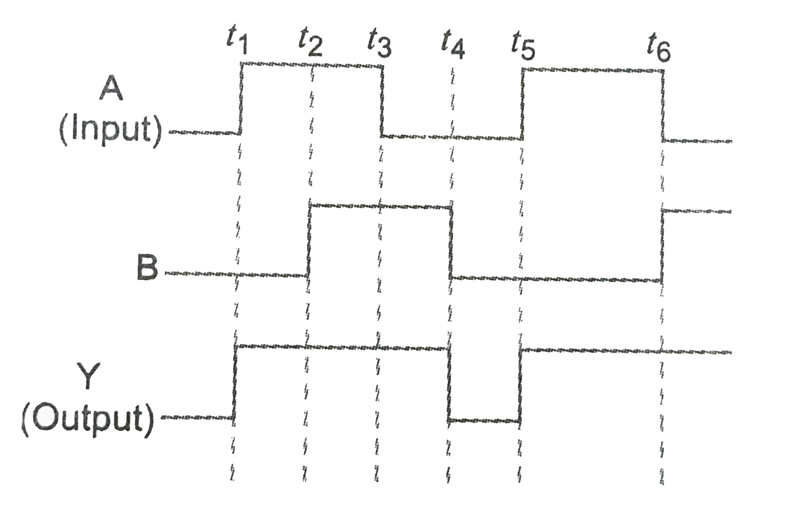
View SolutionSketch the output waveform Y from a NAND gate having following inputs A and B
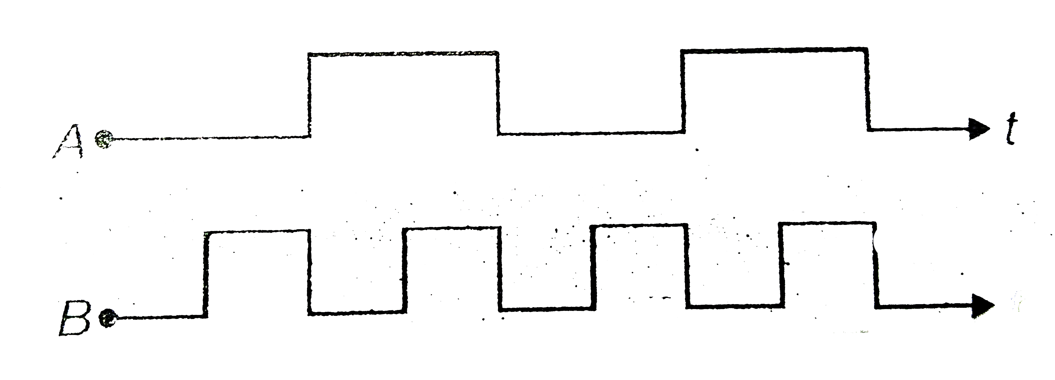
View SolutionSketch the output wavefrom Y from a NAND gate having following inputs A and B
View SolutionA student has to use an appropriate number of (i) NAND gates (only) to get the output y1 (ii) NOR gates (only) to get the output y2 from two given input A and B as shown in the Fig.
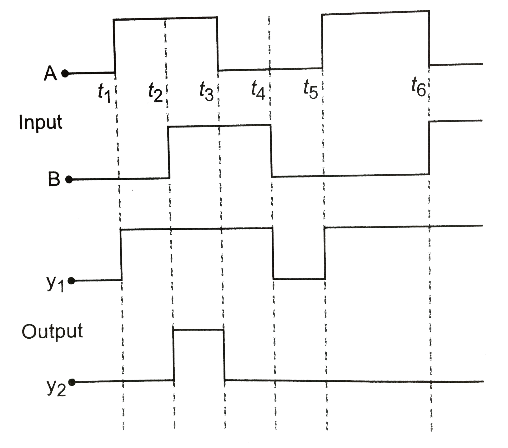
Identify the 'equivalent gate' needed in each case. Show how one can connect an appropriate number of (i) NAND (ii) NOR gates respectively in the two cases to gat the equivalent gates.
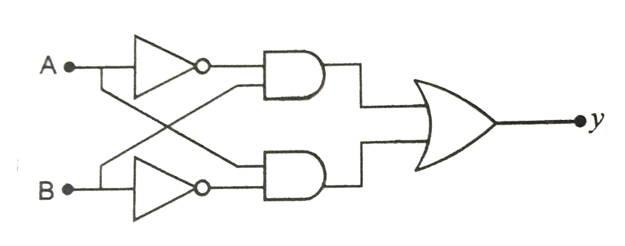
View SolutionFind the Boolean expression of the output y in terms of the input A and B for the circuit shown in Fig.Name the gate formed.
View SolutionWrite the output waveform of the OR gate for the inputs
View Solution

