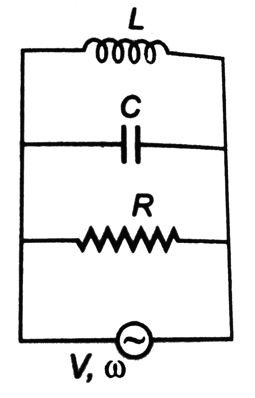
Statement 1: In the purely resistive element of a series LCR, ac circuit the maximum value of rms current increase with increase in the angular frequency of the applied emf.
Statement 2: Imax=εmaxZ,Z=
⎷R2+(ωL−1(ωC)2),
where (Imax) is the peak current in a cycle.
Statement 1 is true, statement 2 is true, Statement 2 is the correct explanation for statement 1.
Statemet 1 is True, Statement 2 is true , Statement 2 is NOT the correct explanation for Statement 1
Statement 1 is True, Statement 2 is False.
Statement 1 is False, Statement 2 is true
The correct Answer is:D
To analyze the given statements, we need to understand the behavior of a series LCR circuit under alternating current (AC) conditions. Let's break down the statements and derive the necessary conclusions step by step.
Step 1: Understanding the Circuit
In a series LCR circuit, we have a resistor (R), an inductor (L), and a capacitor (C) connected in series. The total impedance (Z) of the circuit is given by:
Z=√R2+(ωL−1ωC)2
where:
- ω is the angular frequency of the applied EMF.
Step 2: Analyzing Statement 1
Statement 1: "In the purely resistive element of a series LCR circuit, the maximum value of the RMS current increases with an increase in the angular frequency of the applied EMF."
- In a purely resistive circuit, the impedance Z is simply R.
- The maximum current Imax can be expressed as:
Imax=EmaxZ
- As the frequency increases, the reactive components (inductive and capacitive) do not contribute to the impedance in a purely resistive circuit. Therefore, the impedance remains constant at R.
- Thus, the maximum current does not increase with frequency; it remains constant.
Conclusion for Statement 1: This statement is false.
Step 3: Analyzing Statement 2
Statement 2: "I_{\text{max}} = \frac{E_{\text{max}}}{Z}, Z = \sqrt{R^2 + \left( \omega L - \frac{1}{\omega C} \right)^2}."
- This equation is indeed correct for a series LCR circuit.
- The expression for impedance Z is accurate and reflects the total opposition to current flow in the circuit.
- However, the statement does not directly address the behavior of current with respect to frequency in a purely resistive circuit.
Conclusion for Statement 2: The statement is true in terms of the formula provided, but it does not apply to the context of purely resistive elements as described in Statement 1.
Final Conclusion
- Statement 1: False
- Statement 2: True
In a series LCR circuit, we have a resistor (R), an inductor (L), and a capacitor (C) connected in series. The total impedance (Z) of the circuit is given by:
Z=√R2+(ωL−1ωC)2
where:
- ω is the angular frequency of the applied EMF.
Statement 1: "In the purely resistive element of a series LCR circuit, the maximum value of the RMS current increases with an increase in the angular frequency of the applied EMF."
- The maximum current Imax can be expressed as:
Imax=EmaxZ
- As the frequency increases, the reactive components (inductive and capacitive) do not contribute to the impedance in a purely resistive circuit. Therefore, the impedance remains constant at R.
- Thus, the maximum current does not increase with frequency; it remains constant.
Statement 2: "I_{\text{max}} = \frac{E_{\text{max}}}{Z}, Z = \sqrt{R^2 + \left( \omega L - \frac{1}{\omega C} \right)^2}."
- The expression for impedance Z is accurate and reflects the total opposition to current flow in the circuit.
- However, the statement does not directly address the behavior of current with respect to frequency in a purely resistive circuit.
- Statement 1: False
- Statement 2: True
Topper's Solved these Questions
- ALTERNATING CURRENTBOOK - CENGAGE PHYSICS ENGLISHCHAPTER - ALTERNATING CURRENTEXERCISE - Exercises Linked Comprehension
25 Videos
- ALTERNATING CURRENTBOOK - CENGAGE PHYSICS ENGLISHCHAPTER - ALTERNATING CURRENTEXERCISE - Exercises Integer
4 Videos
- ALTERNATING CURRENTBOOK - CENGAGE PHYSICS ENGLISHCHAPTER - ALTERNATING CURRENTEXERCISE - Exercises Multiple Correct
5 Videos
- ATOMIC PHYSICSBOOK - CENGAGE PHYSICS ENGLISHCHAPTER - ATOMIC PHYSICSEXERCISE - ddp.4.3
15 Videos
Similar Questions
Knowledge Check
The resonant frequency of a series LCR circuit with L=2.0H,C=32μF and R=10Ω is
A20 HzB30 HzC40 HzD50 Hz
The impedance of a series R-C, AC circuit is Z1 for frequency f and Z2 for 2f. If Z1Z2=k, then
View SolutionThe RMS voltage of 10v is applied to a series LCR circuit having R=10ohm,L=1mH and C=10μF. Calculate the current at resonance and Q -value of the circuit at resonance.
View SolutionConsider in L−C−R circuit as shown in figureure with an AC source of peak value V0 and angular frequency ω. Then the peak value of current through the AC
 .
.
View SolutionAn alternating EMF of frequency 12π√LC is applied to a series LCR circuit. For this frequency of the applied EMF,
View SolutionShow that Irms=I0√2, where Irms is the root mean square value of alternating current and I0 the peak value.
View SolutionWhen current (I) in R-L series circuit is constant where L is a pure inductor, The following statements are given

View SolutionAssertion : Angular frequency of LC oscillations is 2rad/s and maximum current in the circuit is 1A. Then, maximum rate of change of current should be 2A/s.
Reason: (dIdt)max=(Imax)ω
View Solution
