The coin remain at rest shown in the fig. This is due to
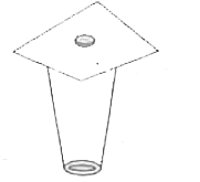
Inertia of rest
two forces act on the coin which balance each other
No unbalanced force acts on it
all of these
The correct Answer is:D
Topper's Solved these Questions
- FORCE AND LAWS OF MOTIONBOOK - CPC CAMBRIDGE PUBLICATIONCHAPTER - FORCE AND LAWS OF MOTIONEXERCISE - UNIT TEST
2 Videos
- FORCE AND LAWS OF MOTIONBOOK - CPC CAMBRIDGE PUBLICATIONCHAPTER - FORCE AND LAWS OF MOTIONEXERCISE - ADDITIONAL EXERCISE
4 Videos
- GRAVITATIONBOOK - CPC CAMBRIDGE PUBLICATIONCHAPTER - GRAVITATIONEXERCISE - ADDITIONAL QUESTIONS (MATCH THE FOLLOWING)
1 Videos
Similar Questions
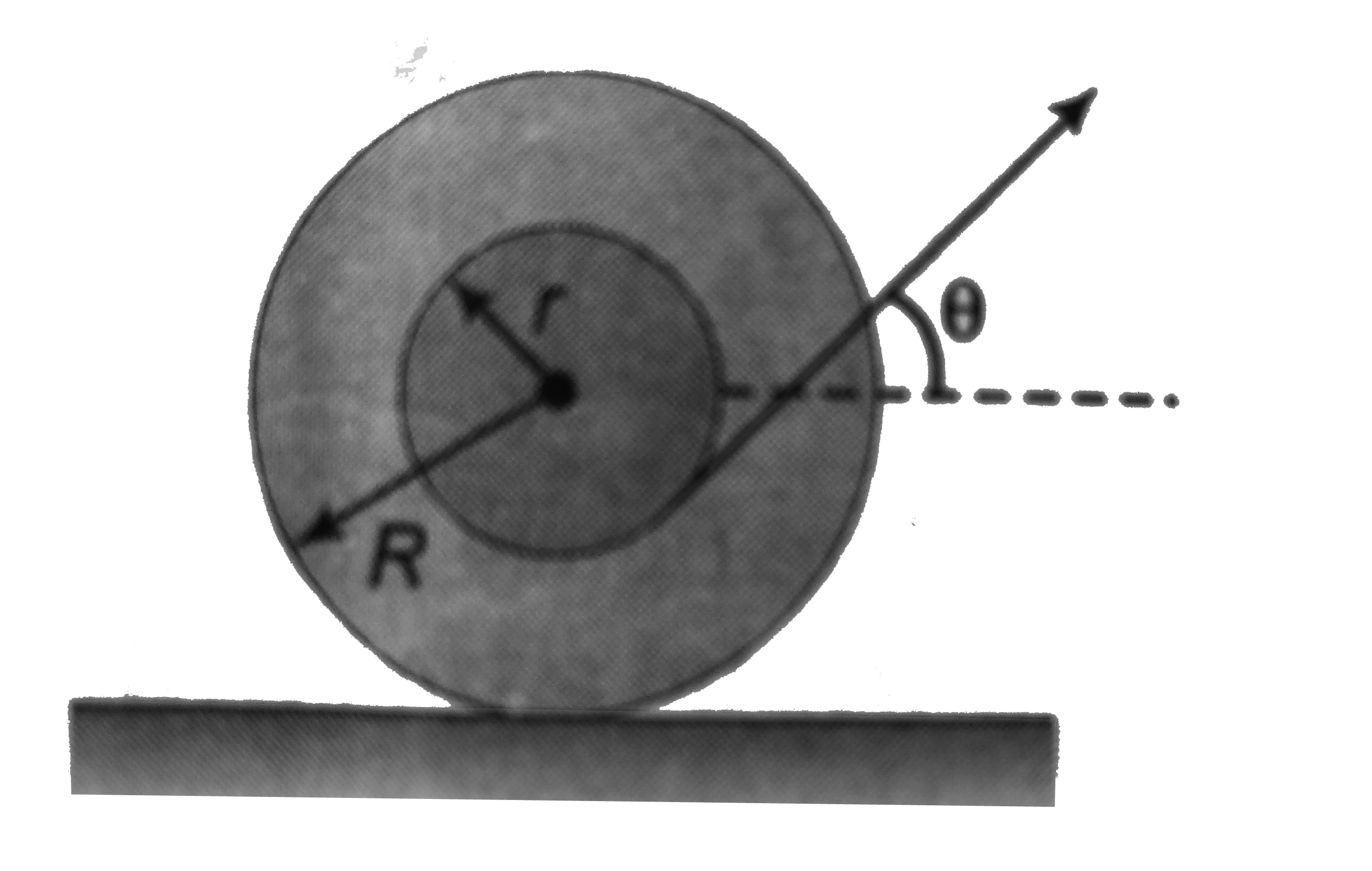
A spool is pulled at an angle θ with the horizontal on a rough horizontal surface as shown in the figure. If the spool remains at rest, the angle θ is equal to
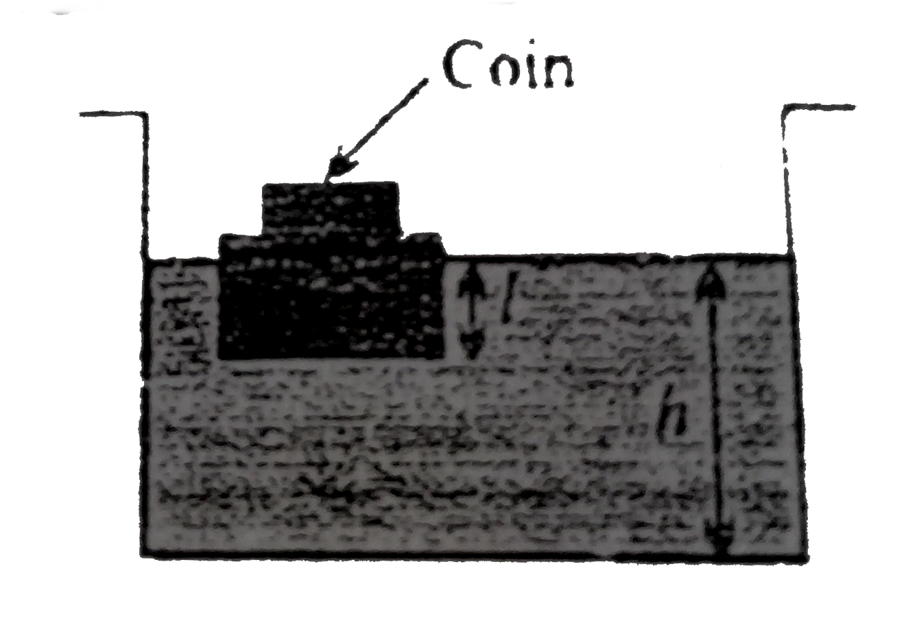
View SolutionA wooden block, with a coin placed on its top, floats in water as shown in figure. The distance l and h are shown there. After some time the coin falls into the water. Then
View Solution
Knowledge Check
A stock of identical coins are placed on a scale as shown in the figure. The thickness of a coin is _______
 A1.8cmB18mmC1.8mmD0.18m
A stock of identical coins are placed on a scale as shown in the figure. The thickness of a coin is _______
 A1.8cmB18cmC1.8mmD0.18m
A stock of identical coins are placed on a scale as shown in the figure. The thickness of a coin is _______
 A(a) 1.8 cmB(b)18 mmC(c ) 1.8 mmD(d) 0.18 m
A coin placed on a rotating gramophone disc, remains at rest when it is at a distance of 9 cm from its centre ,the angular velocity of the disc is then tripled .At what distance from the centre ,the coin should be placed , so that it will remain at rest ?
View Solution
A spool is pulled at an angle θ with the horizontal on a rough horizontal surface as shown in the figure. If the spool remains at rest, the angle θ is equal to
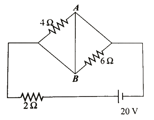
View SolutionIn the circuit shown in Fig. 7.45,
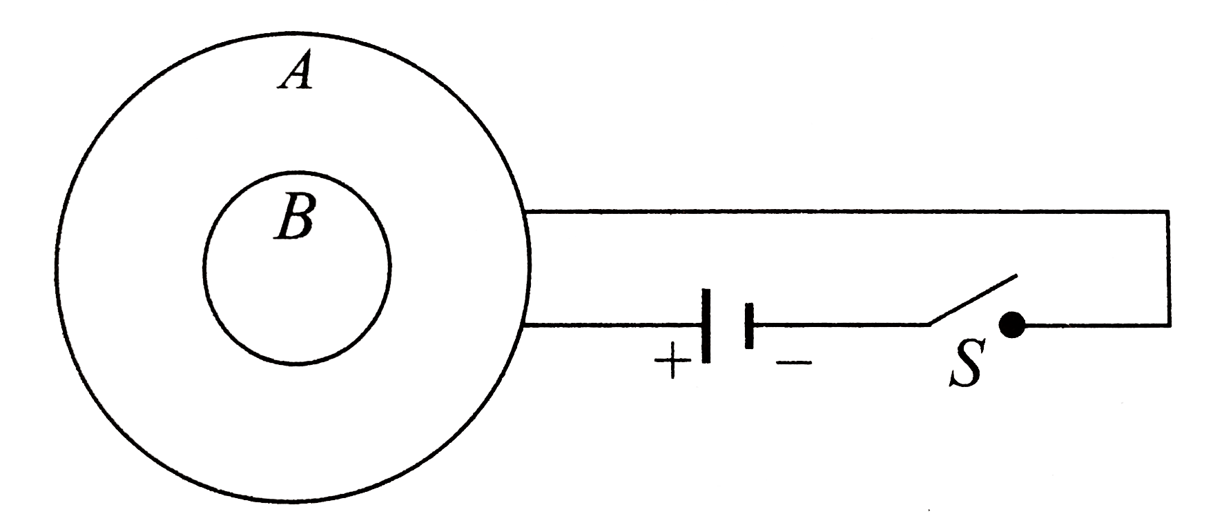
View SolutionThere are two coils A and B as shown in Fig.
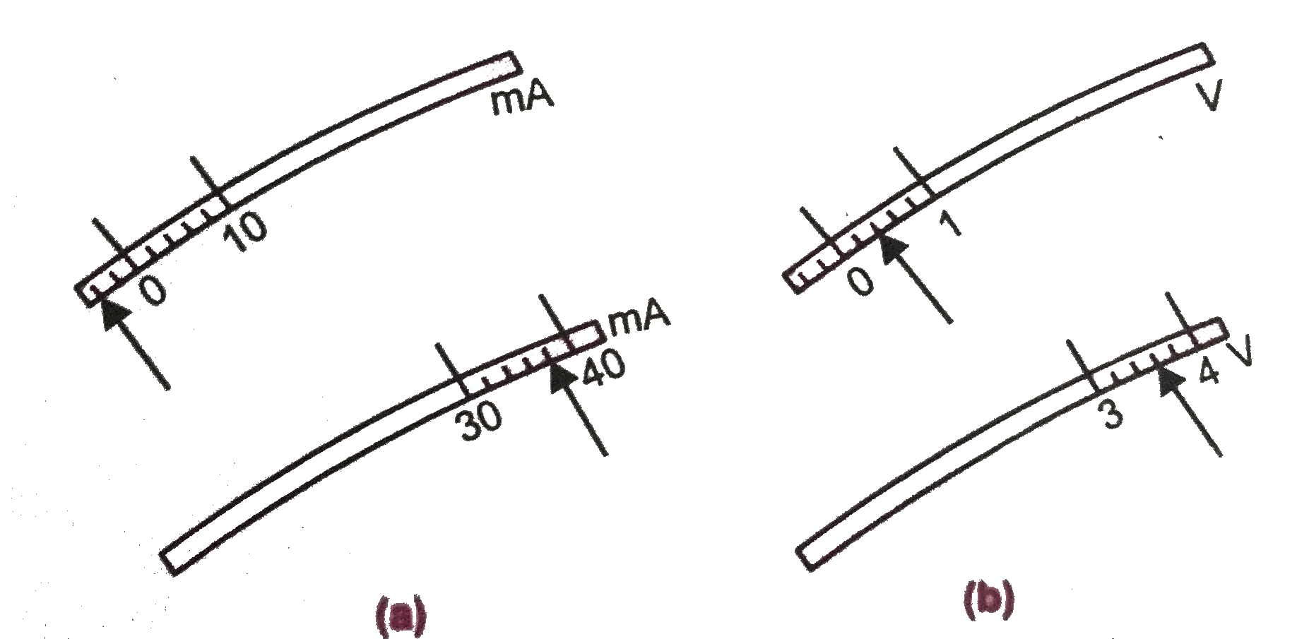
View SolutionThe rest positions of the needles in a milliammeter and voltmeter not in use are as shown in (Fig. 3.61)(a). When a student uses these in his experiment, the readings of the needles are in the positions shown in (Fig. 3.61)(b). Find the corrected values of current and voltage in the experiment.
 .
.
View Solution
