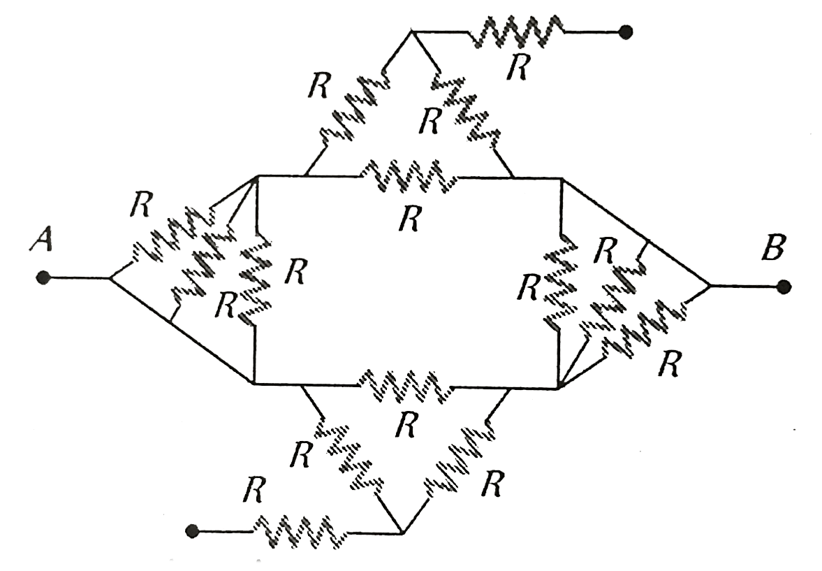
The equivalent resistance between A and B in fig. at steady state will be
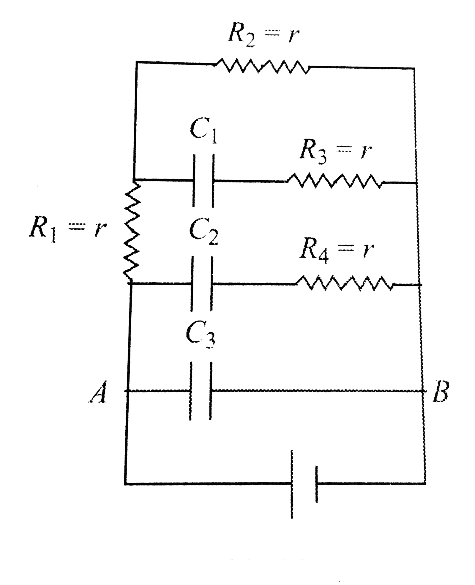
A
2r
B
35r
C
53r
D
none of the above
Video Solution
Text Solution
The correct Answer is:A
At t= 0, the potential difference across the top 2μF capacitor
is 0. Therefore, I=10/2=5A.
|
Updated on:21/07/2023
Topper's Solved these Questions
- BOOK - CENGAGE PHYSICS ENGLISHCHAPTER - ELECTRIC CURRENT AND CIRCUITEXERCISE - Multiple Correct16videos
ELECTRIC CURRENT AND CIRCUIT
- BOOK - CENGAGE PHYSICS ENGLISHCHAPTER - ELECTRIC CURRENT AND CIRCUITEXERCISE - Comprehension35videos
ELECTRIC CURRENT AND CIRCUIT
- BOOK - CENGAGE PHYSICS ENGLISHCHAPTER - ELECTRIC CURRENT AND CIRCUITEXERCISE - Subjective29videos
ELECTRIC CURRENT AND CIRCUIT
- BOOK - CENGAGE PHYSICS ENGLISHCHAPTER - ELECTRIC CURRENT & CIRCUITSEXERCISE - Kirchhoff s law and simple circuits15videos
ELECTRIC CURRENT & CIRCUITS
- BOOK - CENGAGE PHYSICS ENGLISHCHAPTER - ELECTRIC FLUX AND GAUSS LAWEXERCISE - MCQ s38videos
ELECTRIC FLUX AND GAUSS LAW
Similar Questions
Equivalent resistance between A and B is
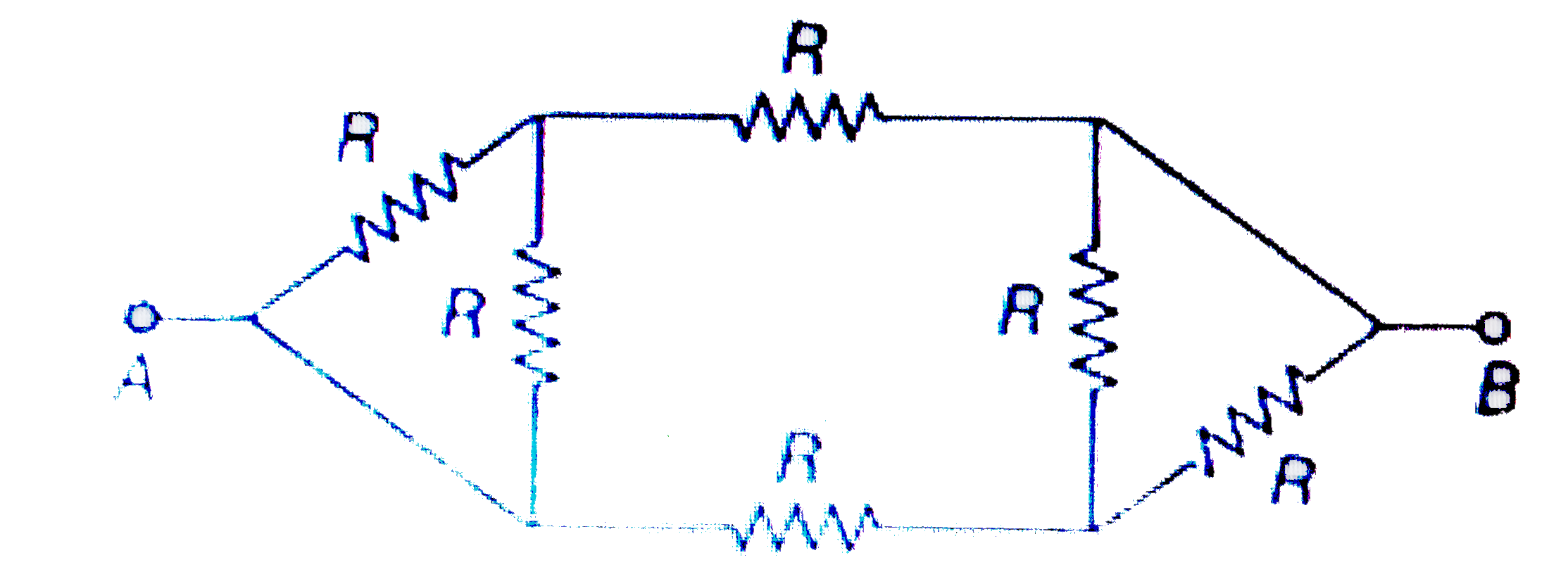 View Solution
Equivalent resistance between A and B in Fig. is
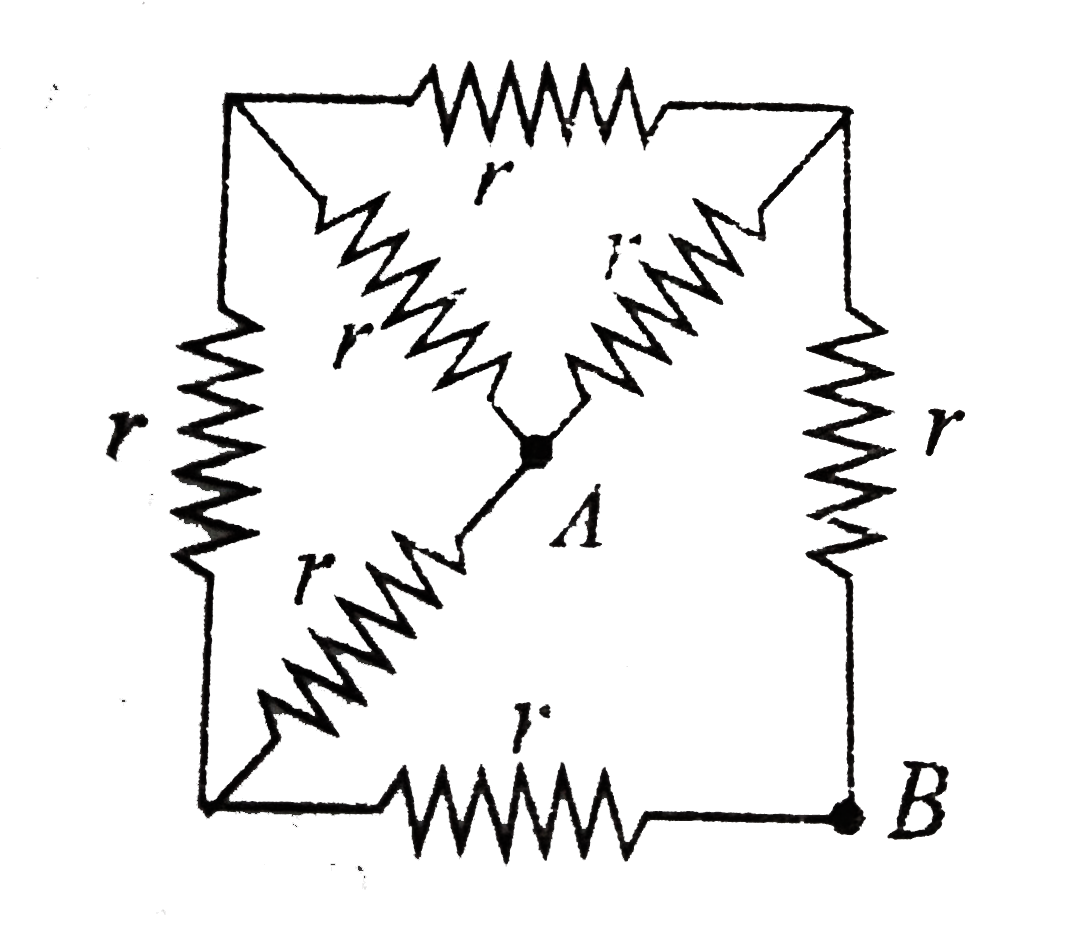 View Solution
Find equivalent resistance between A and B
 View Solution
Find equivalent resistance between A and B
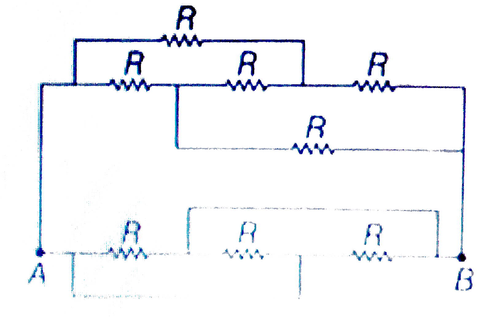 View Solution
Find equivalent resistance between A and B
 View Solution
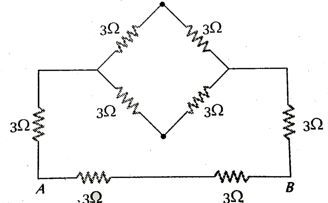
Equivalent resistance between A and B will be
 View Solution
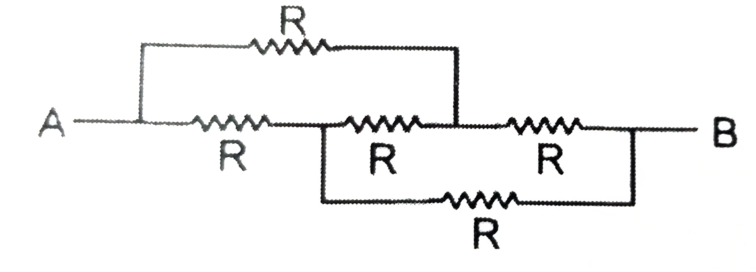
Find the equivalent resistance between A and B
 View Solution
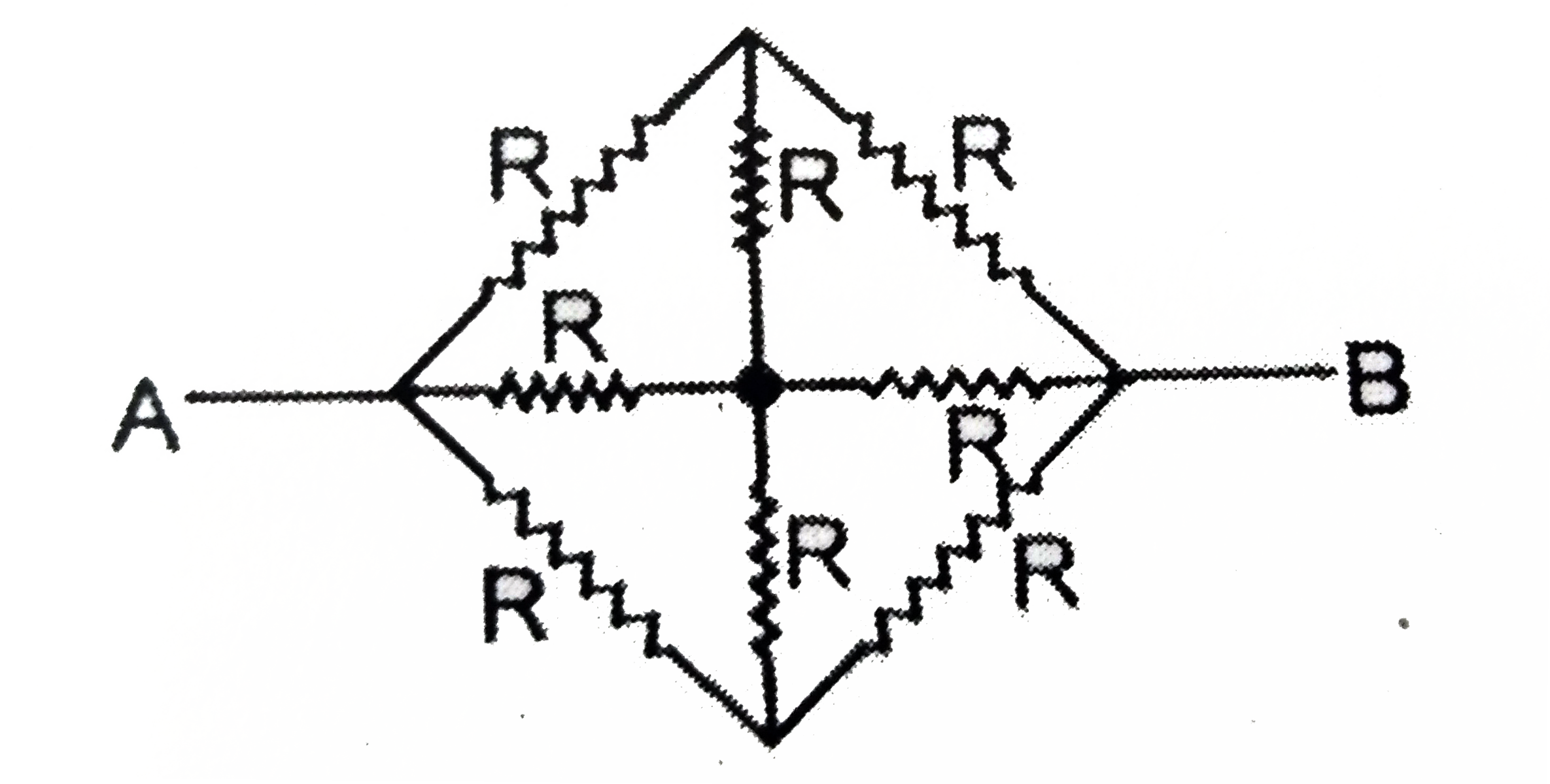
Find the equivalent resistance between A and B
 View Solution
Find the equivalent resistance between A and B.
 View Solution
Find the equivalent resistance between A and B.
 View Solution

