The ideal diodes D1 and D2 are to be connected in the positions shown in the circuit shown below
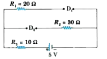
calculate the current in the circuit
(i) when p side of D1 is connected to resistance R1 and p side of D2 is connected to resistance R2
(ii) when n side of D1 connected to resistance R1 and n side of D2 is connected to resistance R2
(i) The given arrangement is shown below :
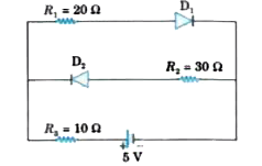
In this case D1 becomes forward d biased and D2
becomes forward biased and D2 becomes reverse biased So , the circuit can be d simplified as shown under.
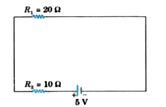
Current flowing in the circuit is
I=5R1+R2=520+10=530=0.167A
(ii) The given arrangement is shown below
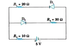
In this case D1 becomes reverse biased and D2 becomes forward biased So, the circuit can be simplified as shown under.
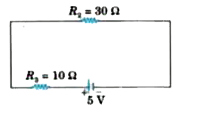
Current in the circuit will be
I=5R2+R3=530+10=54=0.125A
Topper's Solved these Questions
- SEMICONDUCTOR ELECTRONICS METERIALS DEVICES AND SIMPLE CIRCUITS BOOK - MODERN PUBLICATIONCHAPTER - SEMICONDUCTOR ELECTRONICS METERIALS DEVICES AND SIMPLE CIRCUITS EXERCISE - REVISION EXERCISES (VERY SHORT ANSWER QUESTION)
61 Videos
- SEMICONDUCTOR ELECTRONICS METERIALS DEVICES AND SIMPLE CIRCUITS BOOK - MODERN PUBLICATIONCHAPTER - SEMICONDUCTOR ELECTRONICS METERIALS DEVICES AND SIMPLE CIRCUITS EXERCISE - REVISION EXERCISES (ADDITOINAL QUESTION)
9 Videos
- SEMICONDUCTOR ELECTRONICS METERIALS DEVICES AND SIMPLE CIRCUITS BOOK - MODERN PUBLICATIONCHAPTER - SEMICONDUCTOR ELECTRONICS METERIALS DEVICES AND SIMPLE CIRCUITS EXERCISE - NCERT FILE SOLVED (TEXT BOOK EXERCISES )
30 Videos
- RAY OPTICS AND OPTICAL INSTRUMENTSBOOK - MODERN PUBLICATIONCHAPTER - RAY OPTICS AND OPTICAL INSTRUMENTSEXERCISE - CHAPTER PRACTICE TEST
14 Videos
- WAVE OPTICALBOOK - MODERN PUBLICATIONCHAPTER - WAVE OPTICALEXERCISE - CHAPTER PRACTICE TEST
7 Videos
Similar Questions
Knowledge Check
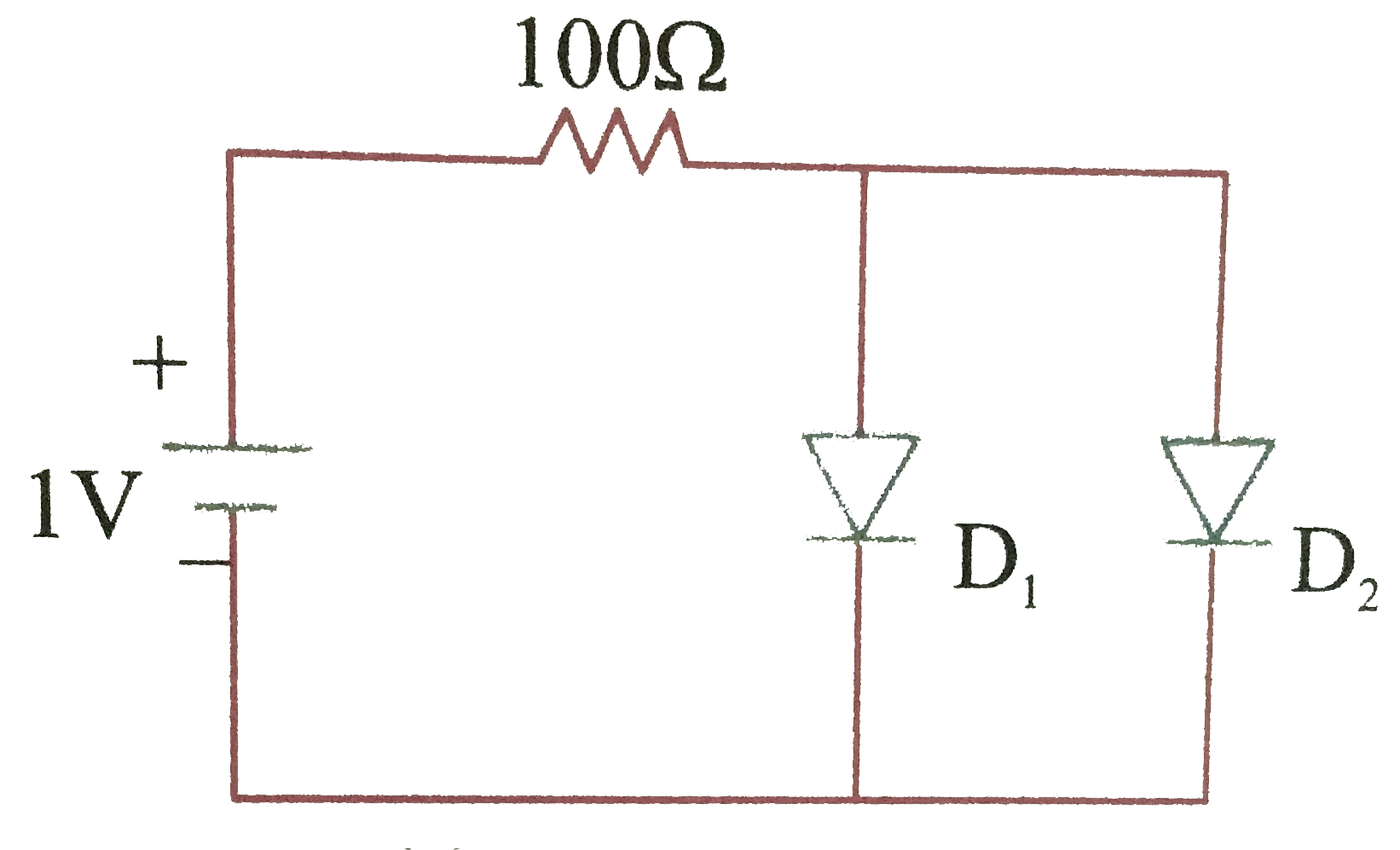
Two ideal diodes D1 and D2 are connected with the battery of 5 volt as shown in figure. Then the current through diode D1 is
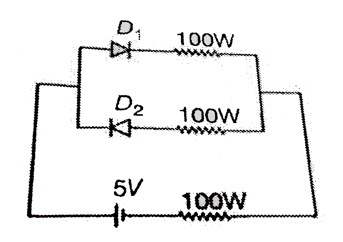 A12.5 mAB25 mACzeroD50 mA
In the circuit shown in the given figure, the resistances R1andR2 are respectively
 A14Ωand40ΩB40Ωand44ΩC40Ωand30ΩD14Ωand30Ω
A cell of constant emf first connected to a resistance R1 and then connected to resistance R2. If power deliverd in both cases is same, then the internal resistance of the cell is
A√R1R2B√R1R2CR1−R22DR1+R22
Assuming that two diodes D1andD2 used in the electric circuit shown are ideal, find out the value the current flowing through 2 Ω resistor .
View SolutionTwo ideal junction diodes D1,D2 are connected as shown in the figure. A 3V battery is connected between A and B. The current supplied by the battery if its positive terminal is connected to A is
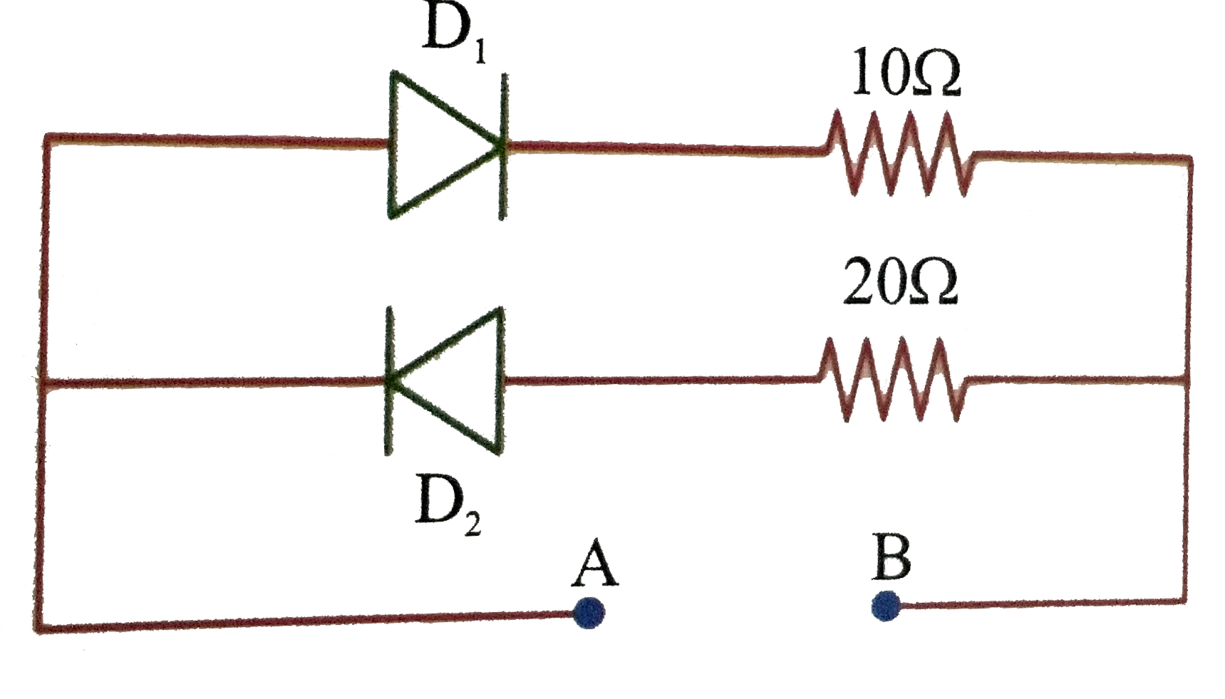 .
.
View SolutionA resistance R1 is connected to a source of constant voltage . On connecting a resistance R2 in series with R1
View SolutionIf a resistanceR2 is connected in parallel with the resistance R in the circuit shown, then possible value of current through R and the possible value of R2 will be
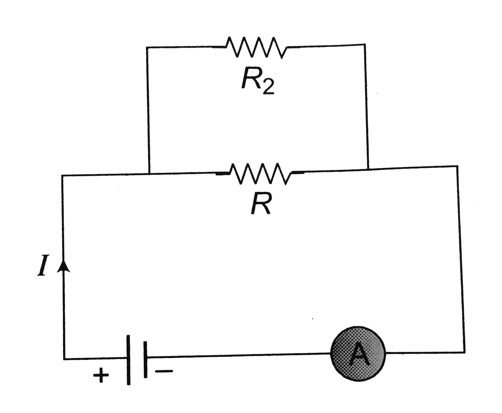
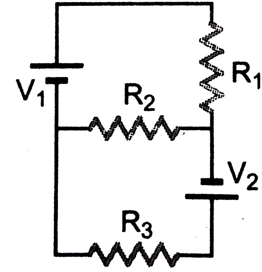
View SolutionTwo ideal batteries of emfV1andV2 and three resistance R1R2andR3 are connected The current in resistance R2 would be zero if
View Solution

 .
.