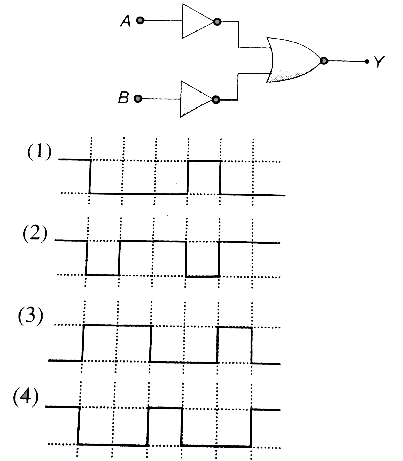
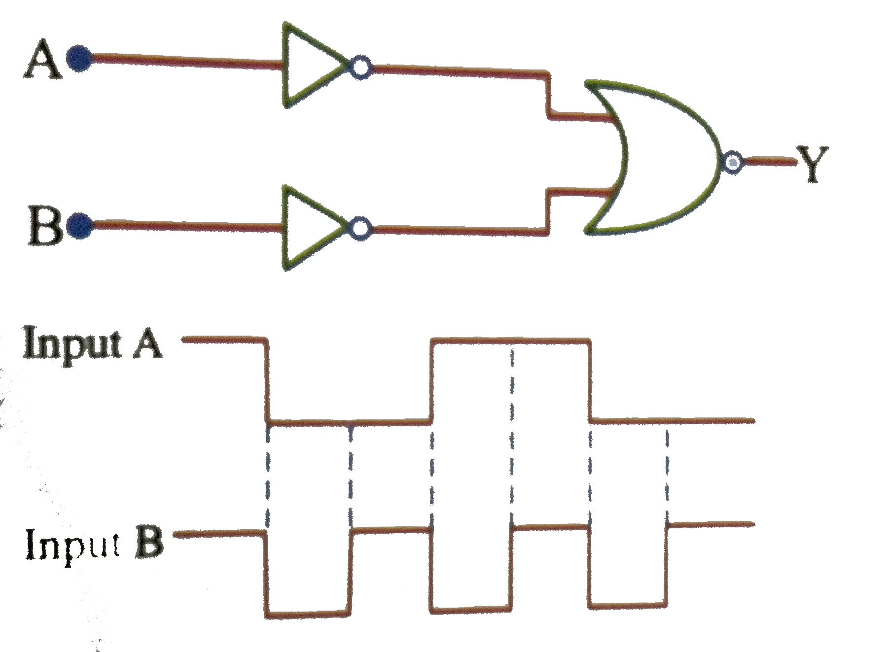
The logic circuit shown below has the input waveform 'A' and 'B' as shown. Pick out the correct output waveform
_E01_490_Q01.png)
Output is :-Solution in Gujrati
_E01_490_O01.png)
_E01_490_O02.png)
_E01_490_O03.png)
_E01_490_O04.png)
The correct Answer is:C
Step by step video & image solution for The logic circuit shown below has the input waveform 'A' and 'B' as shown. Pick out the correct output waveform Output is :- by Physics experts to help you in doubts & scoring excellent marks in Class 11 exams.
Updated on:21/07/2023Topper's Solved these Questions
- SEMICONDUCTORSBOOK - ALLEN CHAPTER - SEMICONDUCTORSEXERCISE - Part-3(Exercise-3)
27 Videos
- PHYSICAL WORLD, UNITS AND DIMENSIONS & ERRORS IN MEASUREMENT BOOK - ALLEN CHAPTER - PHYSICAL WORLD, UNITS AND DIMENSIONS & ERRORS IN MEASUREMENT EXERCISE - EXERCISE-IV
7 Videos
- WAVES AND OSCILLATIONSBOOK - ALLEN CHAPTER - WAVES AND OSCILLATIONSEXERCISE - Part-1(Exercise-05)[B]
42 Videos
Similar Questions
Assertion: Microwave communication is preferred to optical communication
Reason: Microwaves provide large number of channels and bandwidths as compared to optical signals.
View SolutionAssertion : Gravitational forces do not depend on the medium between the masses.
Reason : Mediating particle responsible for gravitational force is graviton.
View SolutionA string of length 0.4m and mass 10−2kg is clamped at one end . The tension in the string is 1.6N. The identical wave pulses are generated at the free end after regular interval of time , Δt . The minimum value of Δt , so that a constructive interference takes place between successive pulses is
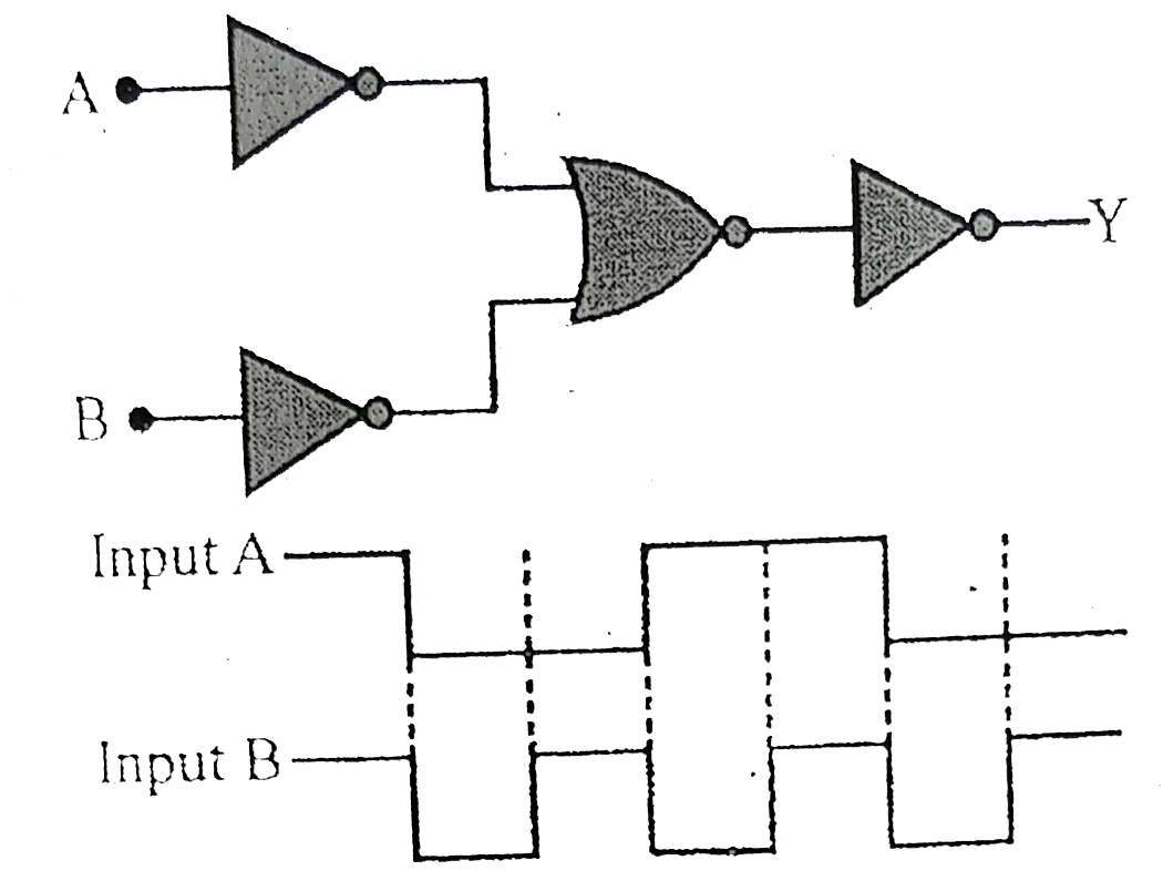
View SolutionThe logic circuit shown belows has the input waveforms 'A' and 'B' as shown. Pick out the correct output waveform
View SolutionThe logic circuit shown below has the input waveforms 'A' and 'B' as shown. Pick out the correct output waveform .
View SolutionThe logic circuit shown below has the input waveform 'A' and 'B' as shown. Pick out the correct output waveform Output is :-
View SolutionThe logic circuit shown has the input waveforms 'A' and 'B' as shown. Pick out the CORRECT output waveform:-
View SolutionThe logic circuit shown below has the input waveforms ‘A’ and ‘B’ as shown. Pick out the correct output waveform
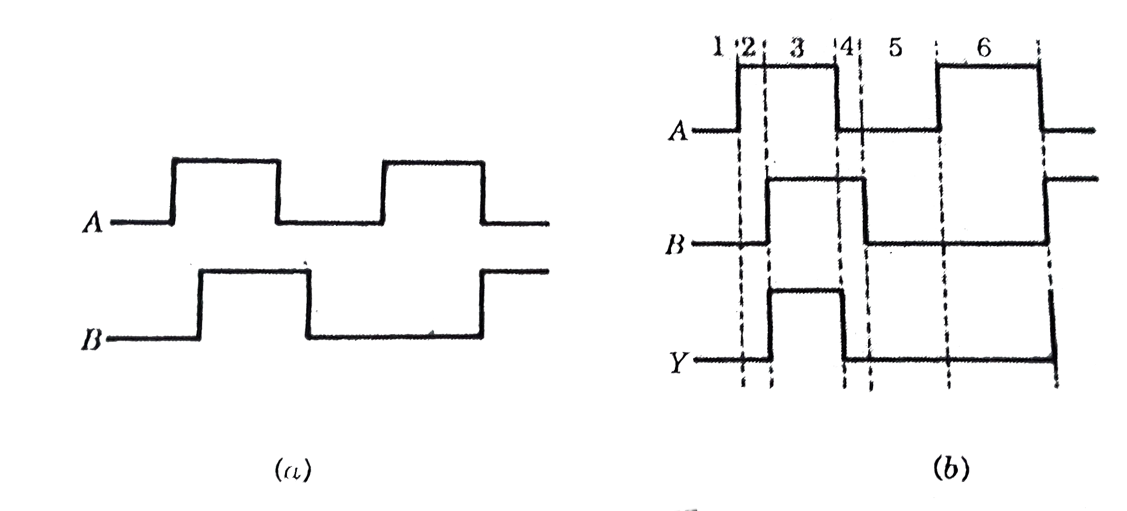
View SolutionTwo input waveforms A and B shown in fig (a) are applied to an AND gate.Write the output waveform.
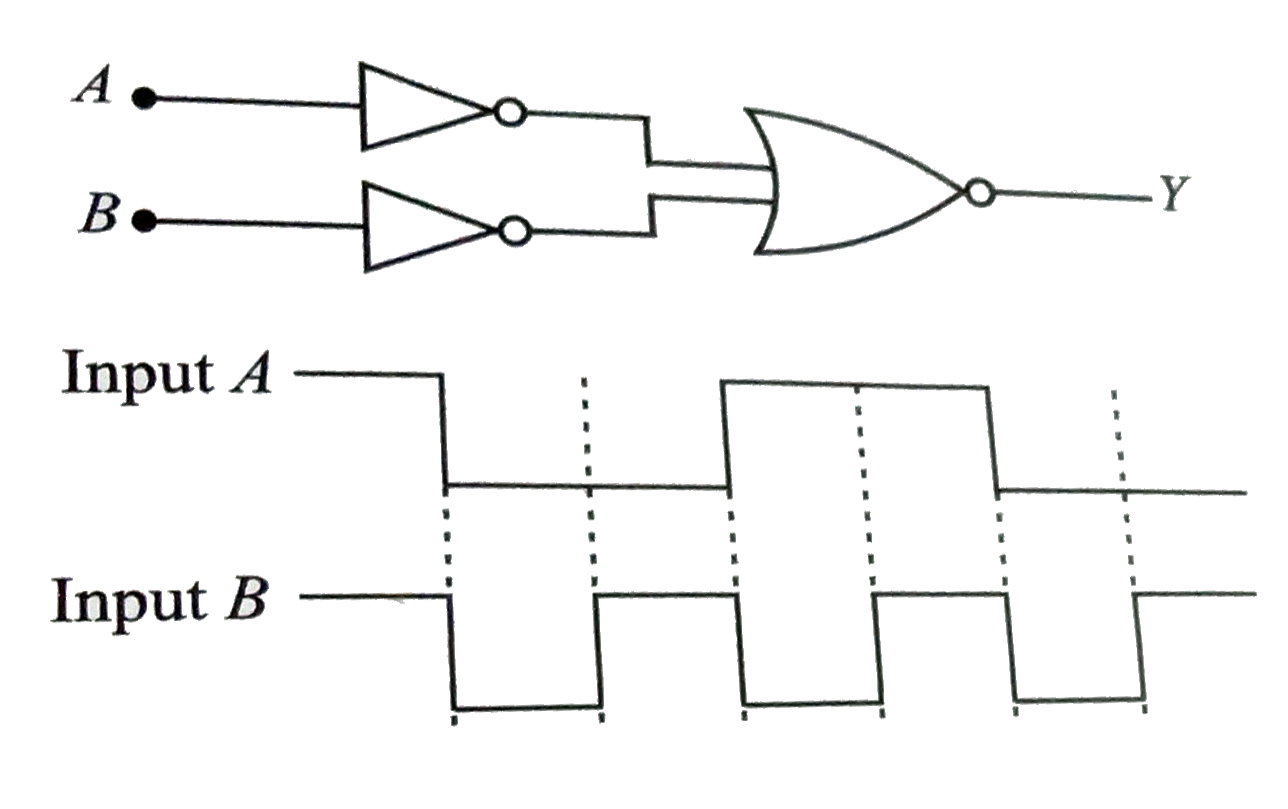
View SolutionThe logic circuit shown below has the inputs waveforms A and B as shown. Pick out the correct output waveform.
View SolutionThe following figure shows a logic gate circuit with two inputs A and B and the output C. The voltage waveforms of A, B and C are as shown below.
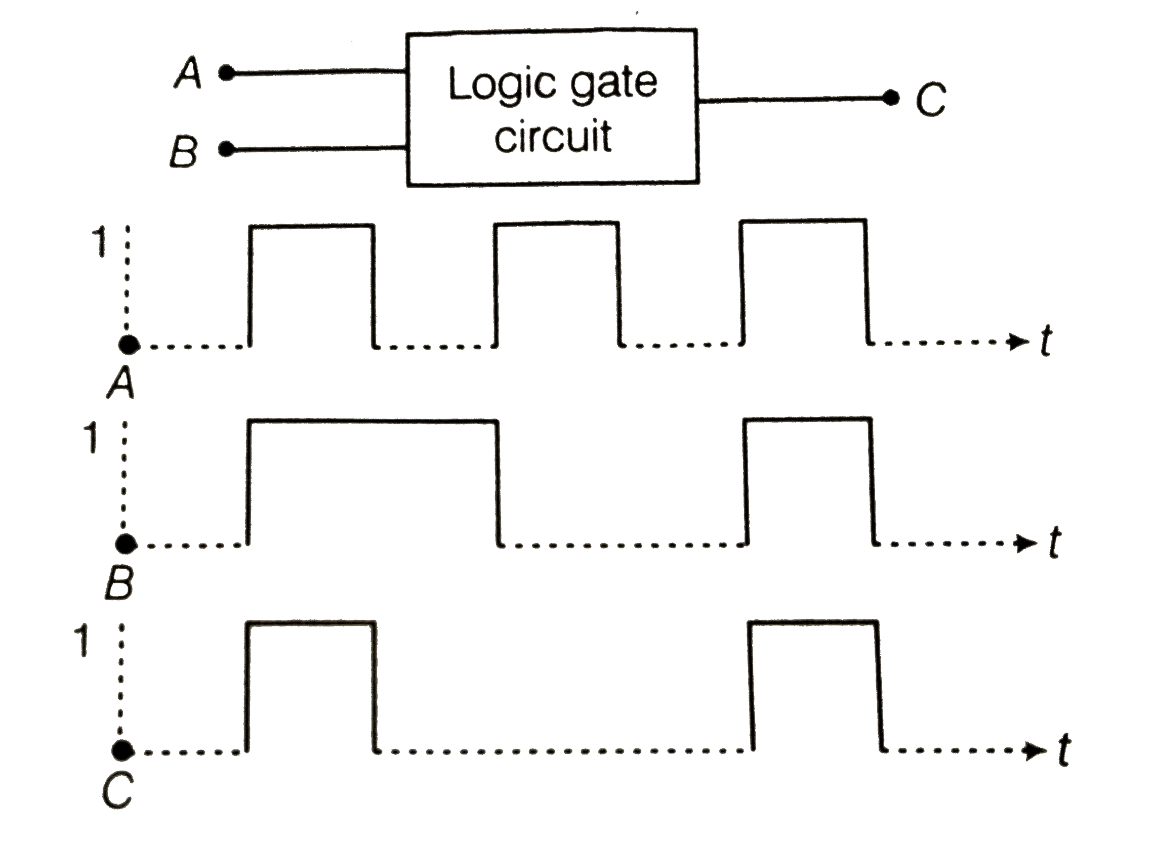
The logic circuit gate is
View SolutionThe logic circuit shown has the input waveforms 'A' and 'B' as shown. Pick out the correct output waveform
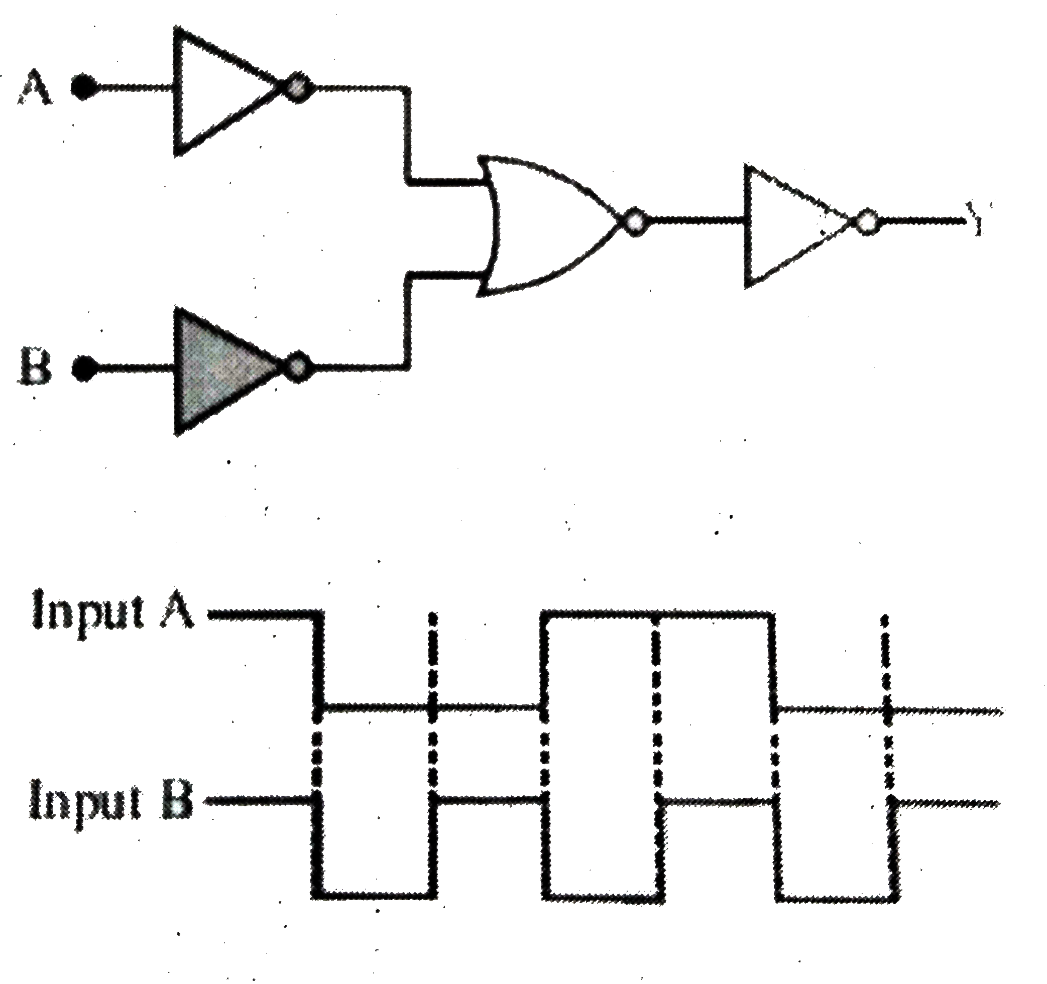
View SolutionThe logic circuit shown below has the input waveform 'A' and 'B' as shown . Pick out the correct output waveform .
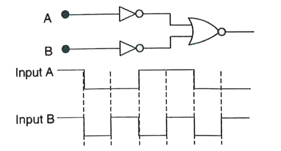
output is :
View SolutionThe following shows a logic gate circuit with two inputs A and B and the output C. The voltage waveforms of A, B and C are as shown below.
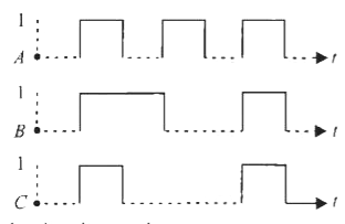
The logic circuit gate is
View SolutionThe logic circuit shown below has the input waveforms 'A' and 'B' as shown. Pick out the correct output waveform
 .
.
View Solution
