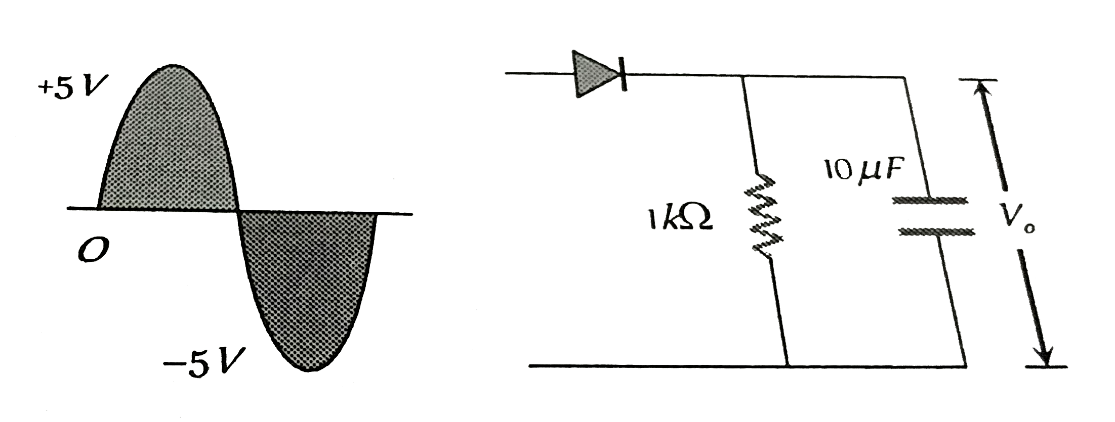
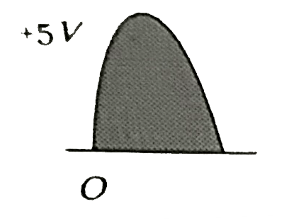
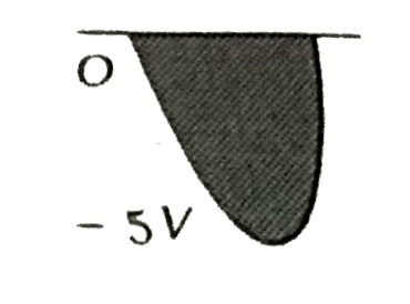
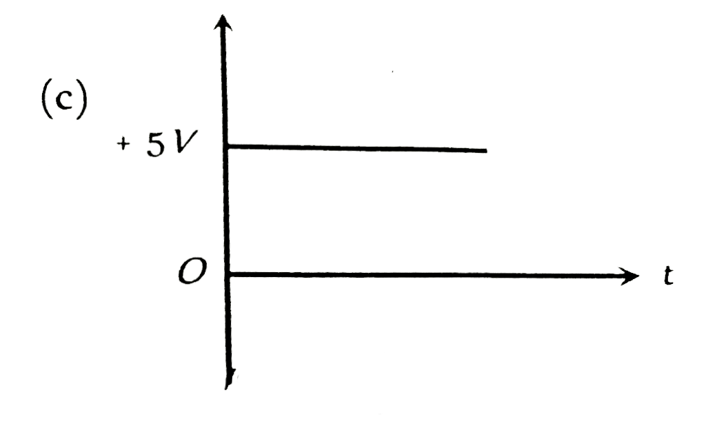
The output in the circuit of figure is taken across a capacitor. It is as shown in figure
A
B
C
D
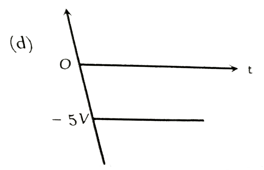
Text Solution
The correct Answer is:C
|
Topper's Solved these Questions
- ELECTRONICSBOOK - ERRORLESS CHAPTER - ELECTRONICSEXERCISE - Selv Evaluation Test
23 Videos
- ELECTRONICSBOOK - ERRORLESS CHAPTER - ELECTRONICSEXERCISE - Objective Questions
12 Videos
- ELECTRON, PHOTON, PHOTOELECTRIC EFFECT AND X-RAYSBOOK - ERRORLESS CHAPTER - ELECTRON, PHOTON, PHOTOELECTRIC EFFECT AND X-RAYSEXERCISE - Self Evaluation Test
3 Videos
- ELECTROSTATICS BOOK - ERRORLESS CHAPTER - ELECTROSTATICS EXERCISE - Ordinary Thinking Objective Questions (Electric Flux and Gauss.s Law)
28 Videos
Similar Questions
Knowledge Check
The output of the given circuit in figure:
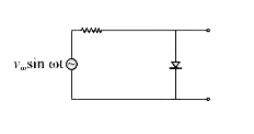 Awould be zero at all times.Bwould be like a half wave rectifier with positive cycles in output.Cwould be like a half wave rectifier with negative cycles in output.Dwould be like that of a full wave rectifier.
The output of the given circuit in Figure
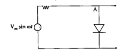 Awould be zero at all times.Bwould be like a half wave rectifier with positive cycles in output.Cwould be like a half wave rectifier with negative cycles in output.Dwould be like that of a full wave rectifier.
A capacitor is connected to a variable source of potential. Current flowing in the circuit and potential across the plates of capacitor at time t are shown in figure.

Capacity of the capacitor isA1 FB2 FC3 FD4 F
A capacitor is connected to a variable source of potential. Current flowing in the circuit and potential across the plates of capacitor at time t are shown in figure.

Capacity of the capacitor is
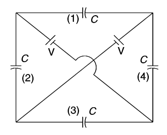
View SolutionIn the circuit shown in the figure, find charge on each capacitor.
View SolutionThe output Y of the logic circuit as shown in figure is

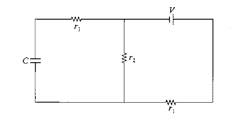
View SolutionIn the circuit shown in figure, the final voltage drop across the capacitor C is :
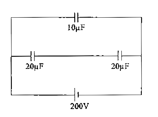
View SolutionIn the circuit shown in figure, charge on 10μF capacitor is given as
View Solution

