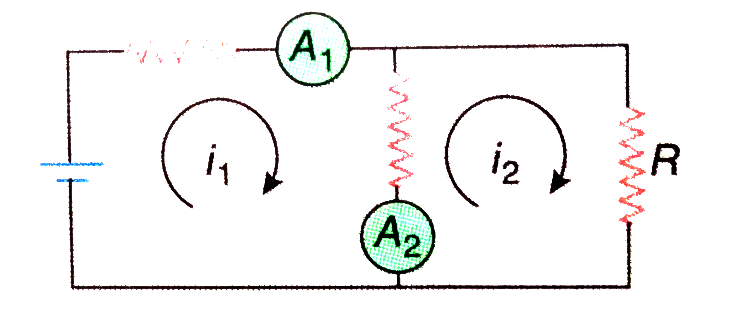
The readings of the two ammeters A1andA2 in the circuit as shown in the are 1.5Aand1.0A respectively . What is the current through the resistance R ?
Text Solution
Currents of the two loops are taken as i2andi2
So , i1=1.5Aandi1−i2=1A
∴ i2=i1−1=1.5−1=0.5A ,
current through the resistance R .
|
Topper's Solved these Questions
- KIRCHHOFF'S LAWS AND ELECTRICAL MEASUREMENT Book:CHHAYA PUBLICATIONChapter:KIRCHHOFF'S LAWS AND ELECTRICAL MEASUREMENT Exercise:NCERT TEXTBOOK QUESTIONS WITH ANSWER HINT
Explore 10 Videos
- KIRCHHOFF'S LAWS AND ELECTRICAL MEASUREMENT Book:CHHAYA PUBLICATIONChapter:KIRCHHOFF'S LAWS AND ELECTRICAL MEASUREMENT Exercise:NCERT EXEMPLAR QUESTIONS WITH ANSWER HINT (MCQ -1)
Explore 2 Videos
- KIRCHHOFF'S LAWS AND ELECTRICAL MEASUREMENT Book:CHHAYA PUBLICATIONChapter:KIRCHHOFF'S LAWS AND ELECTRICAL MEASUREMENT Exercise:Section Related Questions
Explore 14 Videos
- ELEMENTARY PHENOMENA OF ELECTROSTATICS Book:CHHAYA PUBLICATIONChapter:ELEMENTARY PHENOMENA OF ELECTROSTATICS Exercise:EXAMINATION ARCHIVE
Explore 2 Videos
- LIGHT WAVE AND INTERFERENCE OF LIGHT Book:CHHAYA PUBLICATIONChapter:LIGHT WAVE AND INTERFERENCE OF LIGHT Exercise:CBSE SCANNER
Explore 15 Videos
Similar Questions
Knowledge Check
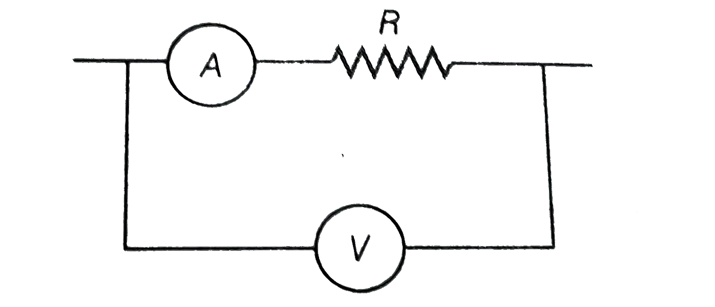
In the circuit shown below, the ammeter A reads 5 A and the voltmeter V reads 20 V The correct value of resistance R is
 Aexactlt 4Ω.Bslightly greater than 4ΩCslightly less than 4ΩDzero
If the ammeter in the given circuit shown in the diagram reads 2A, the resistance R is
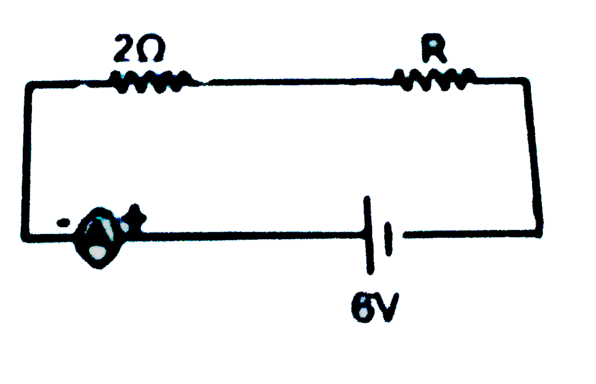 A1ΩB2ΩC3ΩD4Ω
It the ammeter in the given circuit shown in the diagram reads roads 2 A, the resistance R is
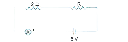 A1ΩB2ΩC3ΩD4Ω
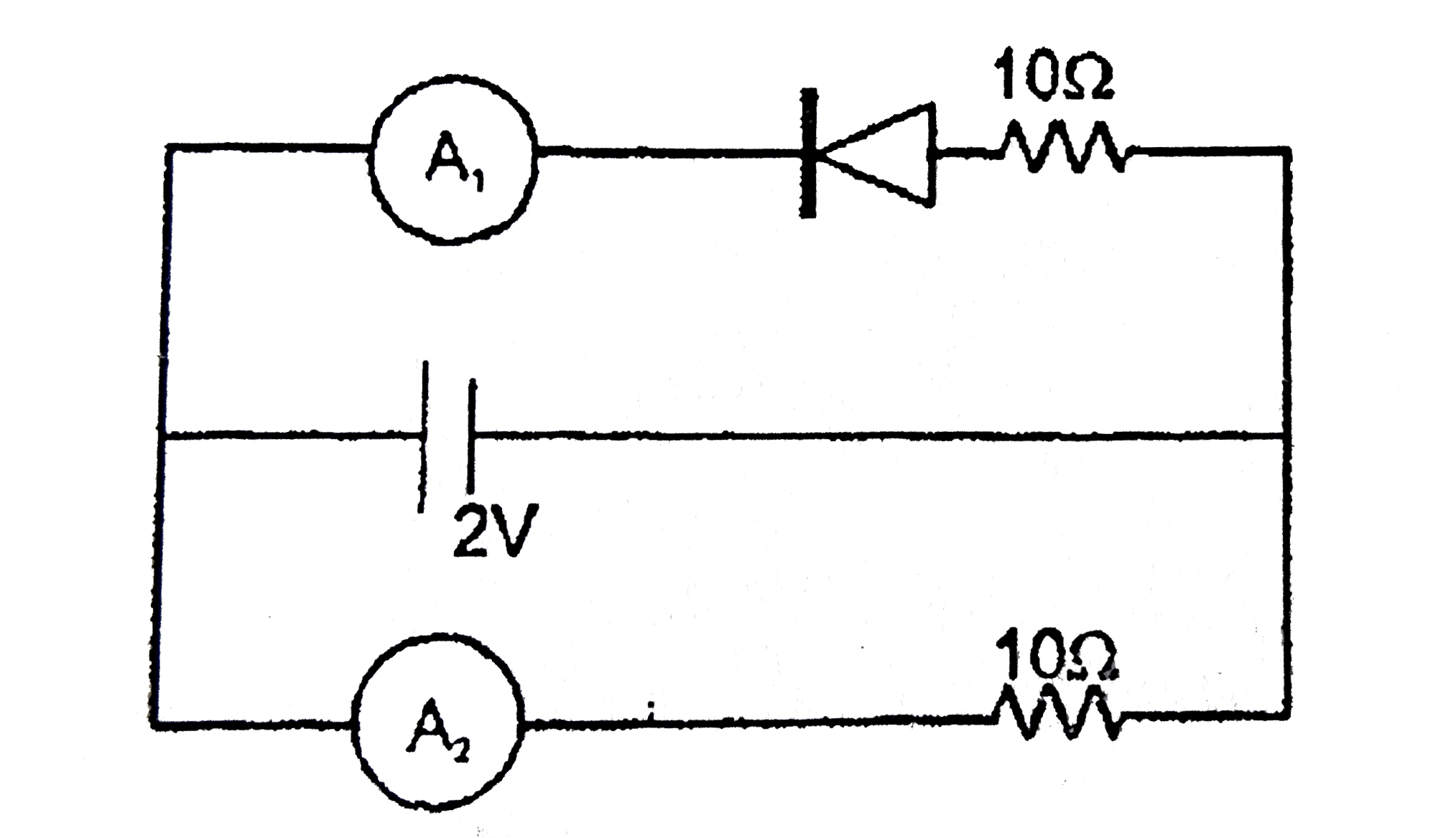
What are the readint of the ammeters A1 and A2 shown in figure. Neglect the resistance of the maters.
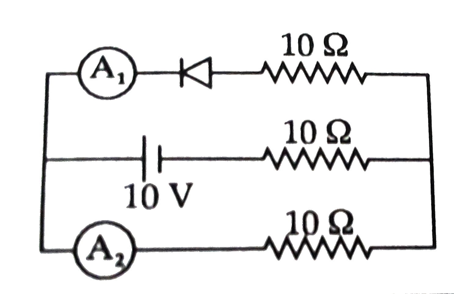
View SolutionIn the figure shown the readings of the ammeters A1andA2 are respectively.
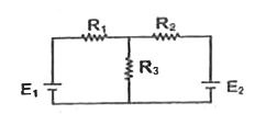
View SolutionIn the circuit shown, E1=7V,E2=7V,R1=R2=1Ω and R3=3Ω respectively. The current through the resistance R3
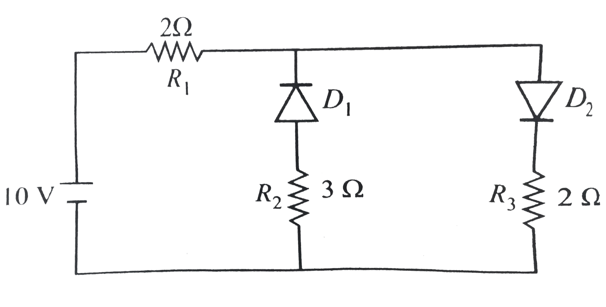
View SolutionThe given circuit has two ideal diodes connected as show in the figure. The current flowing through the resistance R1 will be
View SolutionIn the circuit shown, E1=7V,E2=7V,R1=R2=1Ω and R3=3Ω respectively. The current through the resistance R3

View Solution

