To the terminals marked as XandY in the given circuit, three students connect 4 cells of voltage 1.5V each in three different manners (A),(B), (C) shown in (Fig. 3.62). Find the readings (VA,VB,VC) of the voltmeter, for the three students.
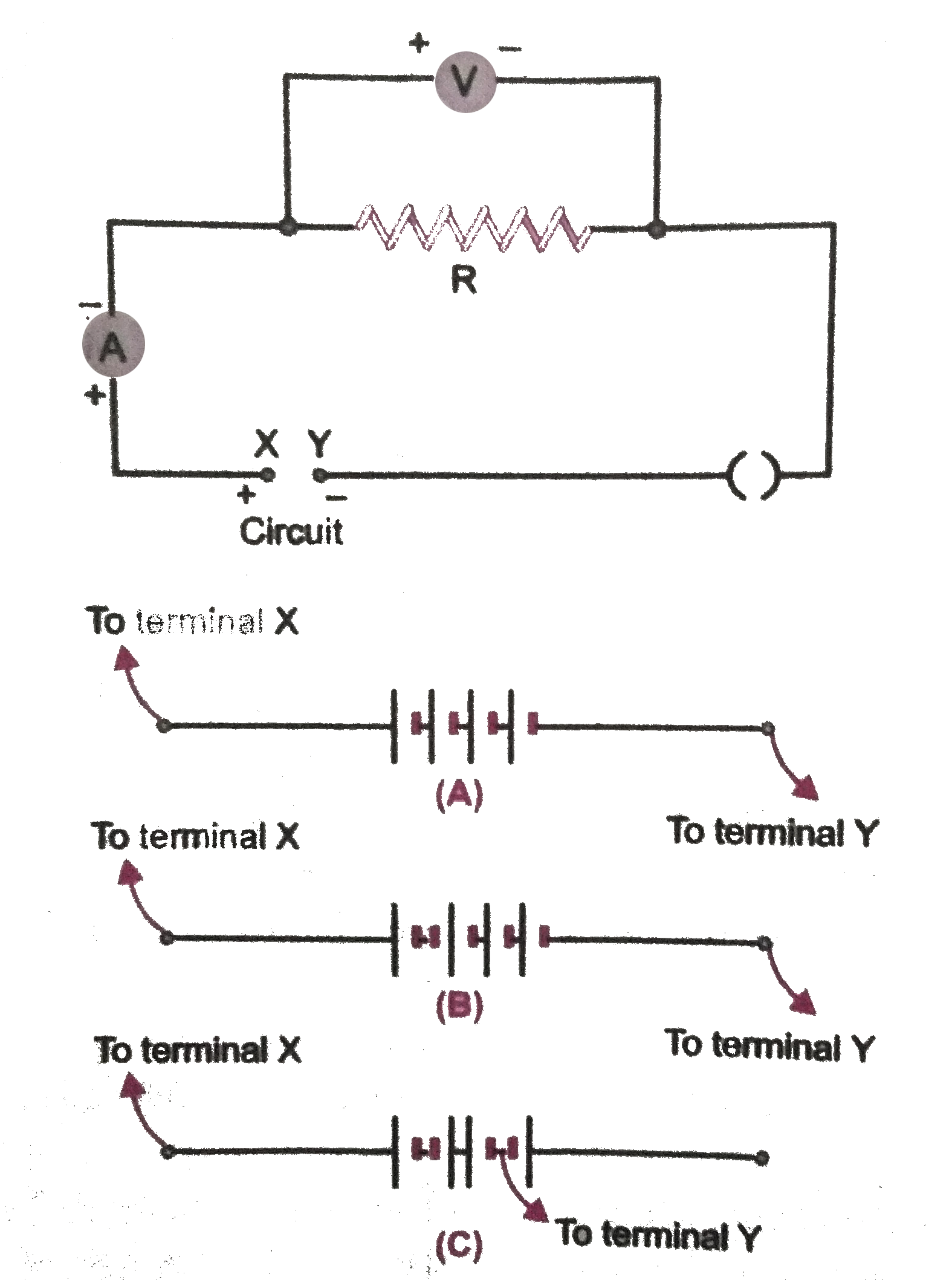 .
.
Video Solution
Text Solution
As in (A), all the four cells are in series, in (B), only two cells are effectively in series and in ( C), onle one cell is effective, VA=6.0V,VB=3.0V,VC=1.5V.
|
Updated on:21/07/2023
Topper's Solved these Questions
Similar Questions
Knowledge Check
- Question 1 - Select One
Three students (A), (B) and (C) connect their two given resistors R1 and R2 in the manners shown below :

They connect the terminals marked X and Y above to the terminals marked X and Y in the circuit given below:
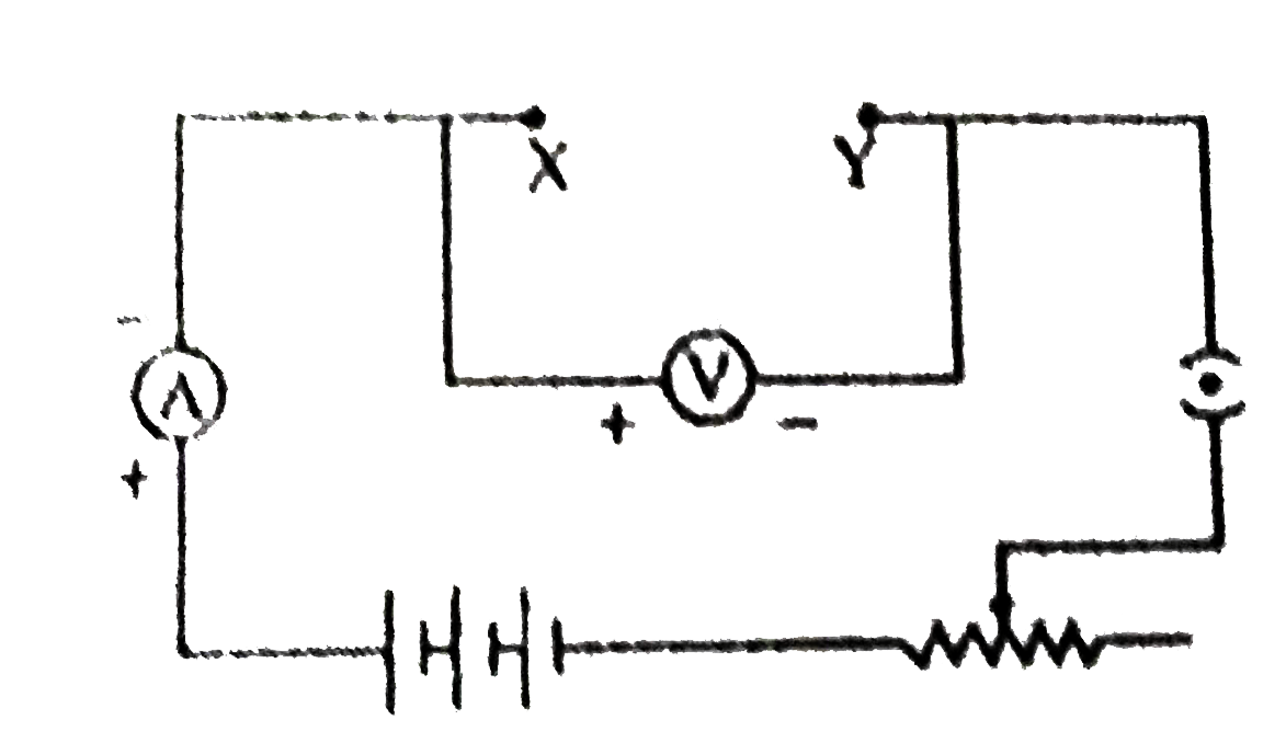
The record the Ammeter readings (I) for different positions of the rheostat and the corresponding Voltmeter readings (V).
The average value of the ratio V/I in their observations would be minimum for :Astudents (A) and (B) onlyBstudents (B) and (C) onlyCstudents (C) and (A) onlyDstudent (A) only - Question 2 - Select One
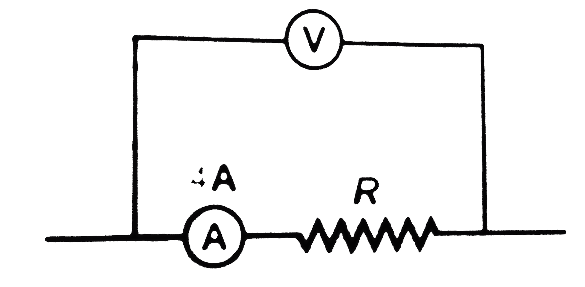
A students connects an ammeter A and a voltmeter V to measure a resistancer as shown in figure. If the voltmeter reads 20V and the ammeter reads 4A, then R is
 Aequal to 5ΩBgreater than 5ΩCless than 5ΩDgreater or less than 5Ω depending upon the direction of current
 - Question 3 - Select One
A student has to connect 4 cells of 2 V each to form a battery of voltage 8 V. The correct way of connecting these cells is shown in figure :
A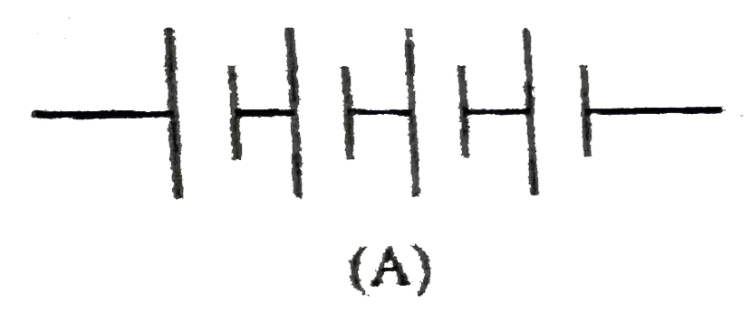 B
B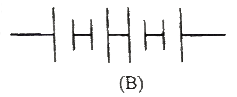 C
C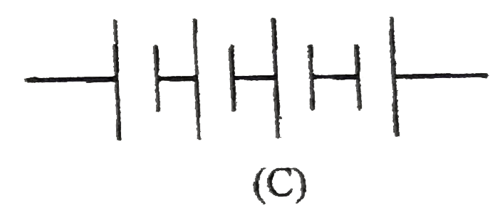 D
D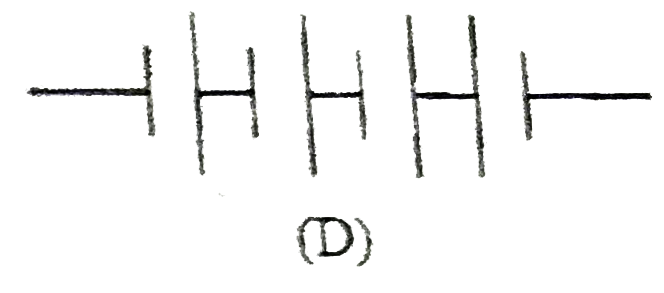
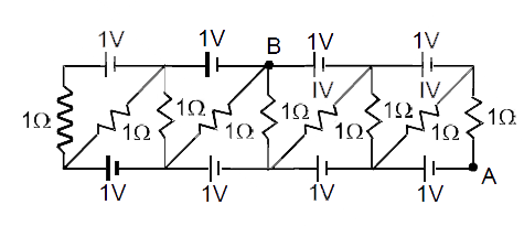
The potential difference VA−VB for the circuit shown in fig. is. −(22/x)V. find the value of x.
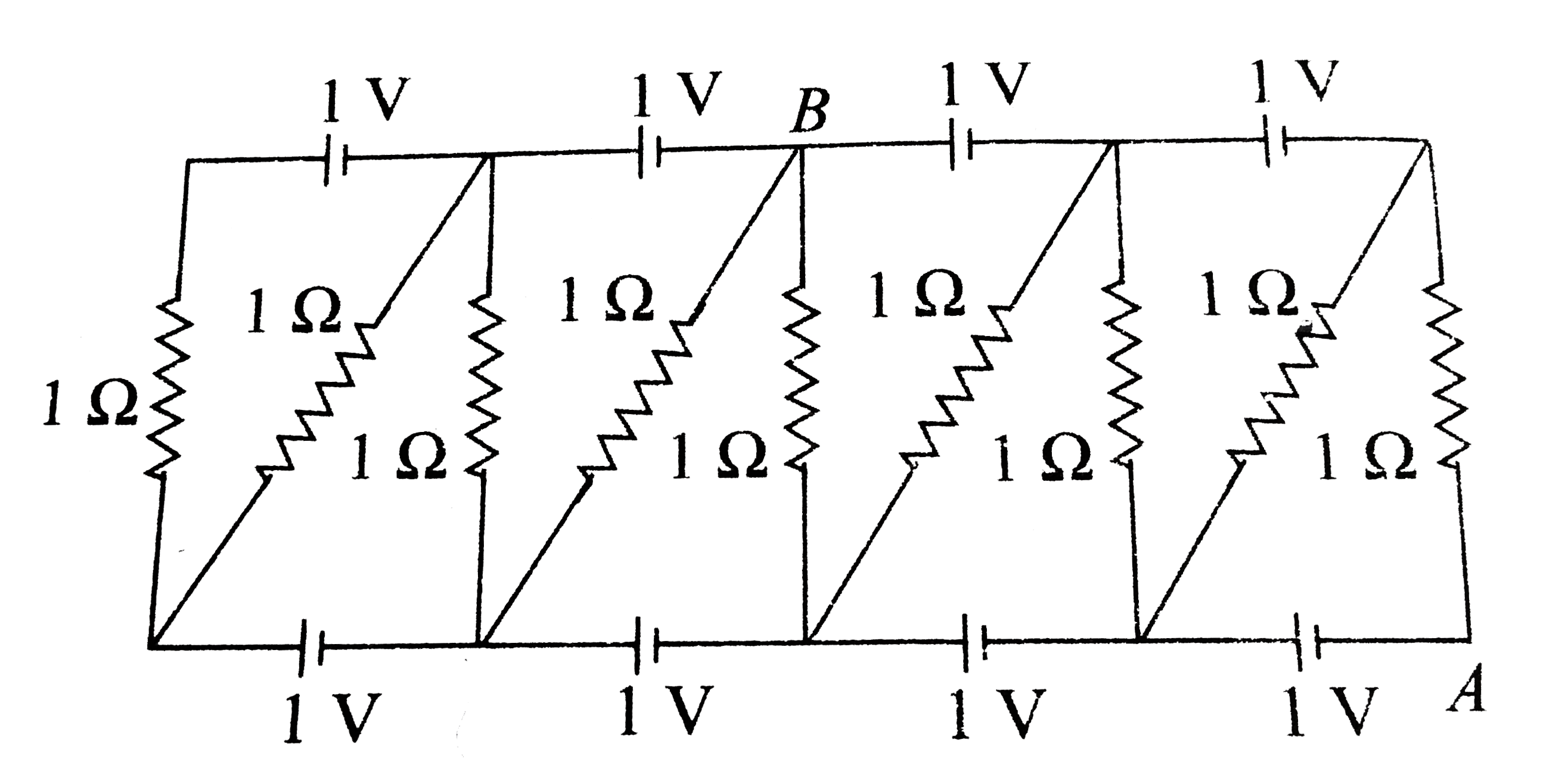 View Solution
In the circuit shown(Fig.) if the diode forward voltage drop is 0.3V, the voltage difference between A and B is :
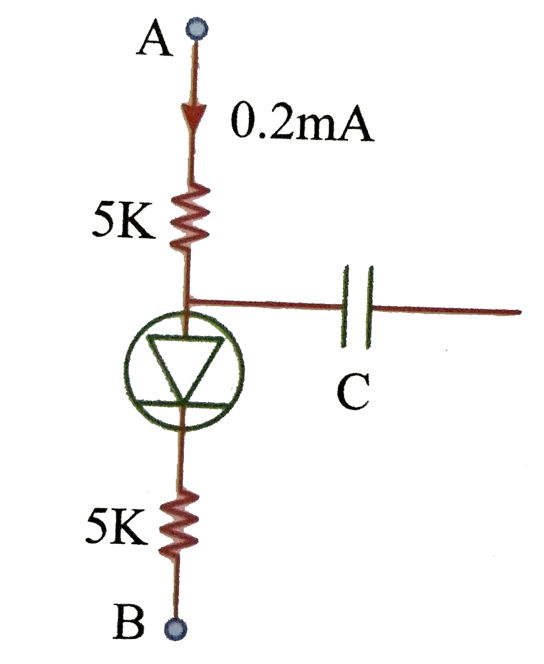 .View Solution
Three batteries are connected as shown in the figure.
Then the total emf in the circuit is ____ V.
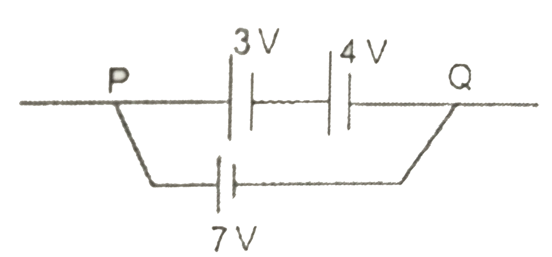 View Solution
In the experiment on finding the equivalent resistance of two resistors, connected in parallel, three students connected the voltmeter in their circuits, in the three ways X, Y and Z shown here.
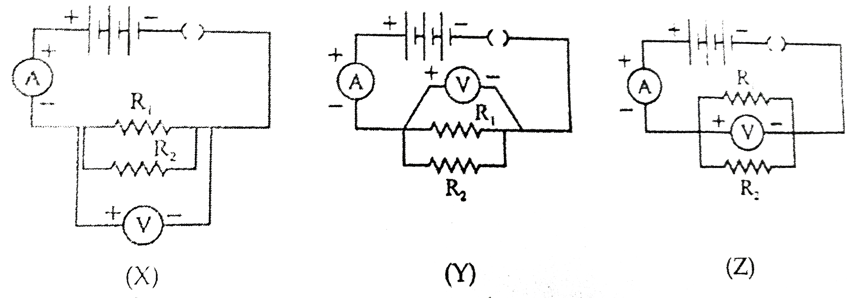
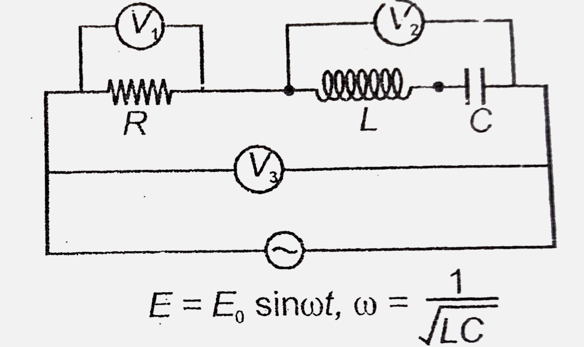
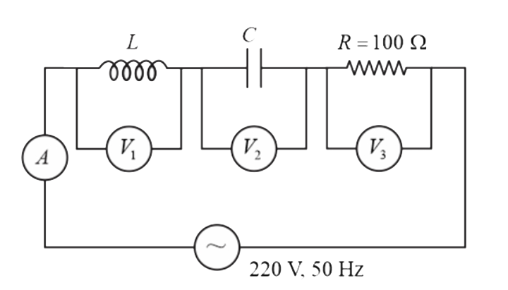
The voltmeter has been correctly connected inView SolutionIn the given circuit the reading of voltmeters V1andV2 are 300 volt each . The reading of the voltmeter V3 and ammeter A are respectively
 View Solution


