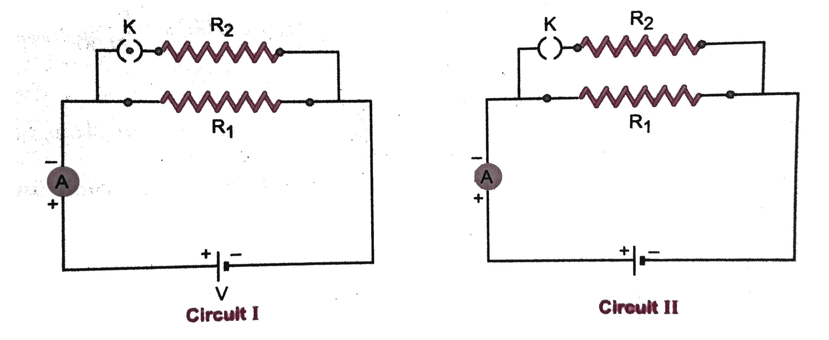
Two electric circuits are shown in (Fig. 3.55). In circuit , the key is closed whereas in circuit , the key is open. Compare the currents and circuit .
 .
.
Video Solution
Text Solution
In circuit , since is closed, are in parallel combination. Their equivalent resistance is given by
Current in the circuit,
In circuit , since is open, the resistance is out of circuit and as such the net resistance in the circuit is .
Current in the circuit, . Thus,
since .
Thus, current in circuit is more than the current in circuit .
|
Topper's Solved these Questions
- ELECTRICITYBOOK - PRADEEPCHAPTER - ELECTRICITYEXERCISE - Value Based Question
4 Videos
- ELECTRICITYBOOK - PRADEEPCHAPTER - ELECTRICITYEXERCISE - Problem For Practice
59 Videos
- ELECTRICITYBOOK - PRADEEPCHAPTER - ELECTRICITYEXERCISE - Based On Practical
10 Videos
- MAGNETIC EFFECTS OF ELECTRIC CURRENTBOOK - PRADEEPCHAPTER - MAGNETIC EFFECTS OF ELECTRIC CURRENTEXERCISE - Mock Test
21 Videos
Similar Questions
Knowledge Check
Find the current I in circuit
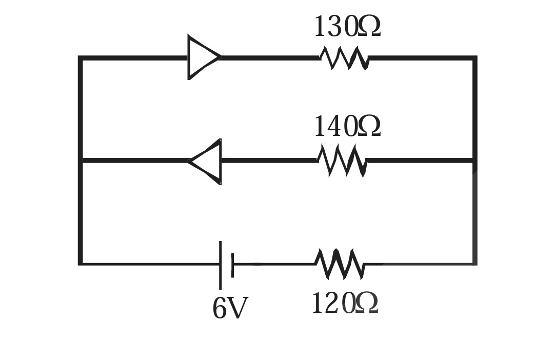 A20 mAB2 mAC0.1 mAD10 mA
The current I in the circuit is
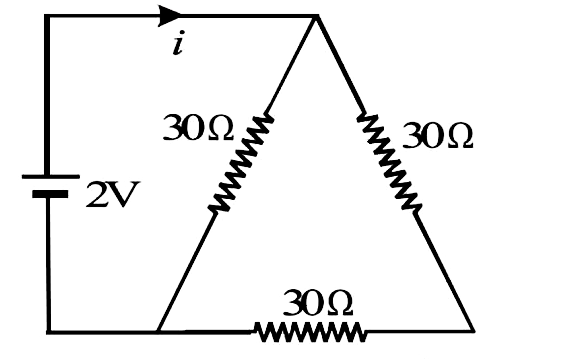 A1/45 AB1/15 AC1/10 AD1/5 A
The current I in the circuit shown is
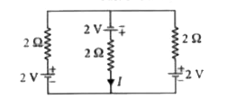 A1.33ABzeroC2.00AD1.00A
The current I shown in the circuit is
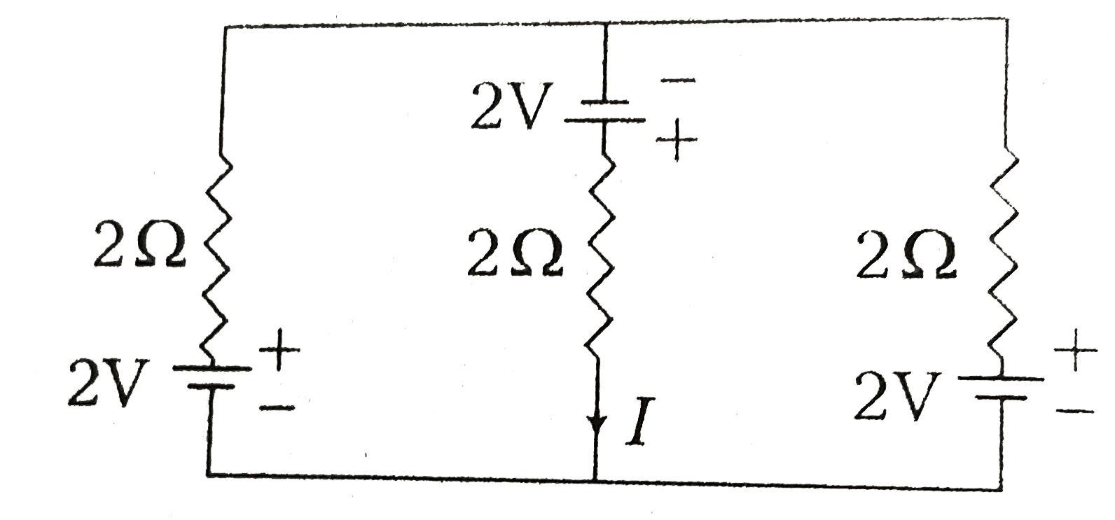
View SolutionShown in the figure is an R−L circuit. Just after the key (K) is closed
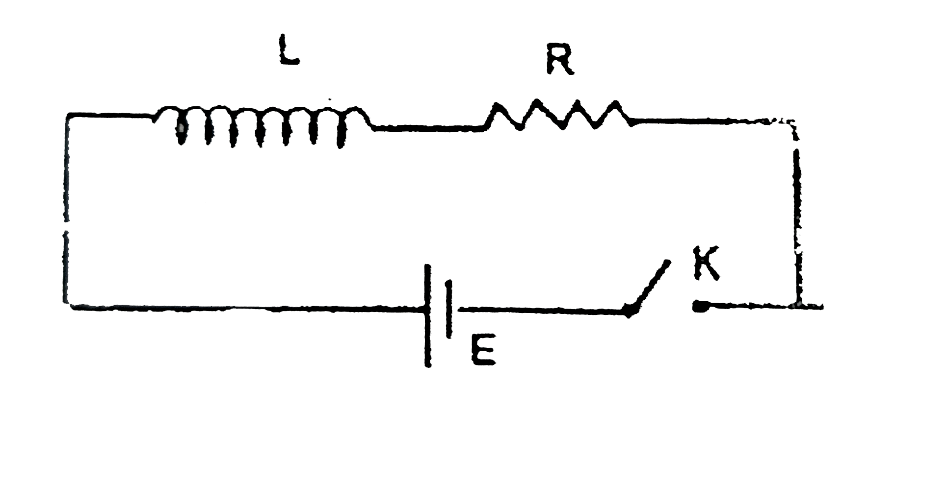
View SolutionThe current I in the adjoining circuit is
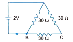
View SolutionThe value of current I in the circuit will be
View SolutionIn the circuit shown, the currents i1 and i2 are
View Solution


