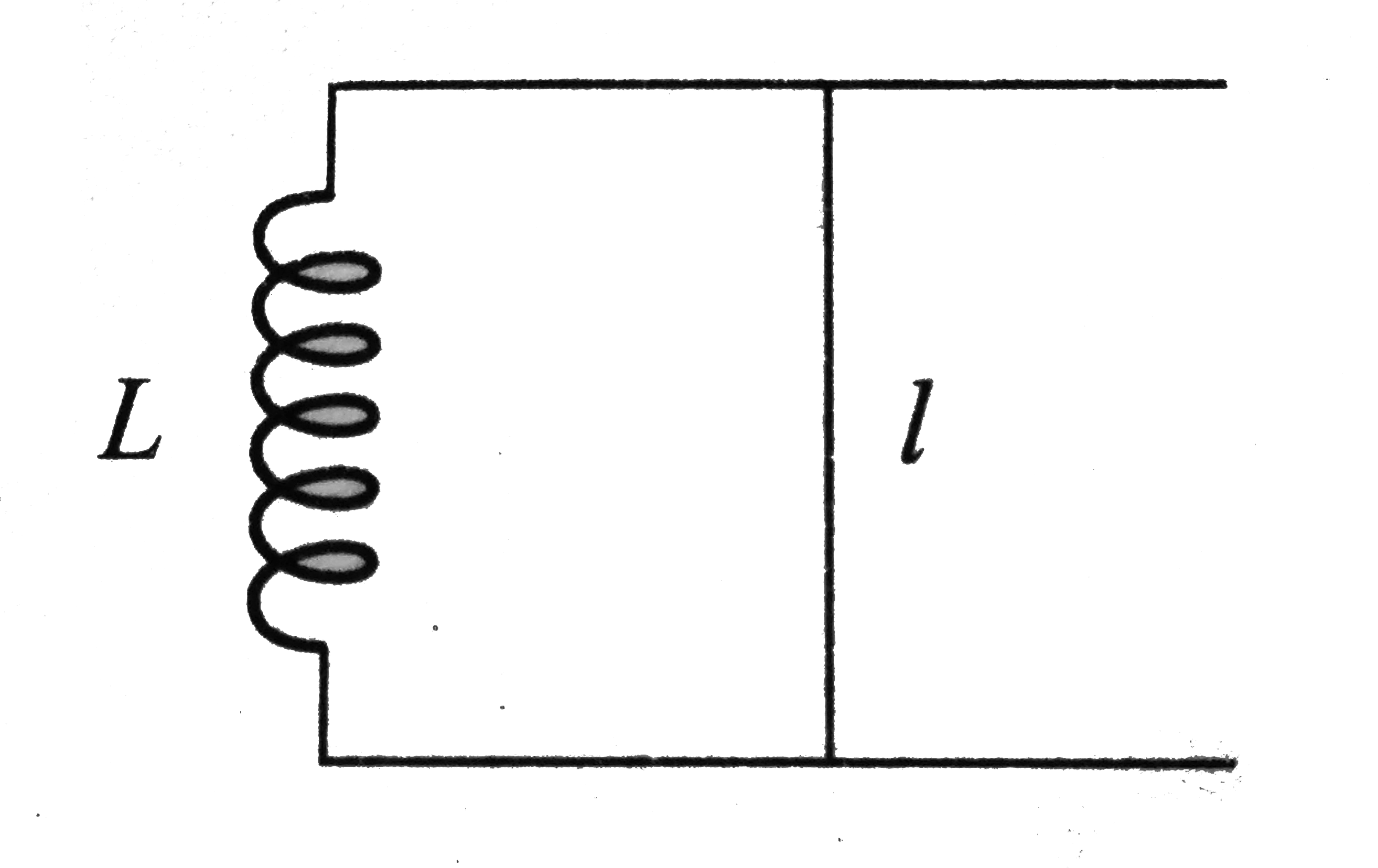
Two parallel resistanceless rails are connected by an inductor of inductance L at one end as shows in Fig. A magnetic field B exists in the space which is perendicular to the plane of the rails. Now a conductor of length l and mass m is placed transverse on the rail and given an inpulse J toward the rightward direction. Then choose the correct option (S).
Velocity of the conductor is half of the initial velocity after a displaacement of the conductor d=√3J2L4B2l2m
Current flowing through the inductor at the instant when velocity of the conductor is half of the initial velocity is i=√3J24Lm
Velocity of the conductor is half of the initial velocity after a displacement of the conductor d=√3J2LB2l2m
Current flowing through the inductor at the instant when velocity of the conductor is half of the initial velocity is i=√3j2mL
The correct Answer is:A, B
Ldidt=Bνl⇒∫di=BlL∫νdt⇒I=BlLx (i)
F=ma⇒−iBl=mνdνdx
⇒−B2l2xL=mνdνdx⇒−B2l2Ld∫0xdx=ν0/2∫ν0νdν
⇒−B2l2d2L=−3ν208,ν0=Jm
⇒d=√3J2L4B2l2m
Put x=d in (i), i=BlL√3J2L4B2l2m=√3J24Lm
Topper's Solved these Questions
- INDUCTANCEBOOK - CENGAGE PHYSICSCHAPTER - INDUCTANCEEXERCISE - Exercises (assertion-reasoning)
2 Videos
- INDUCTANCEBOOK - CENGAGE PHYSICSCHAPTER - INDUCTANCEEXERCISE - Exercises (linked Compreshension)
36 Videos
- INDUCTANCEBOOK - CENGAGE PHYSICSCHAPTER - INDUCTANCEEXERCISE - Exercises (single Correct )
65 Videos
- HEATING EFFECT OF CURRENTBOOK - CENGAGE PHYSICSCHAPTER - HEATING EFFECT OF CURRENTEXERCISE - Thermal Power in Resistance Connected in Circuit
28 Videos
- KINETIC THEORYBOOK - CENGAGE PHYSICSCHAPTER - KINETIC THEORYEXERCISE - Question Bank
31 Videos
Similar Questions
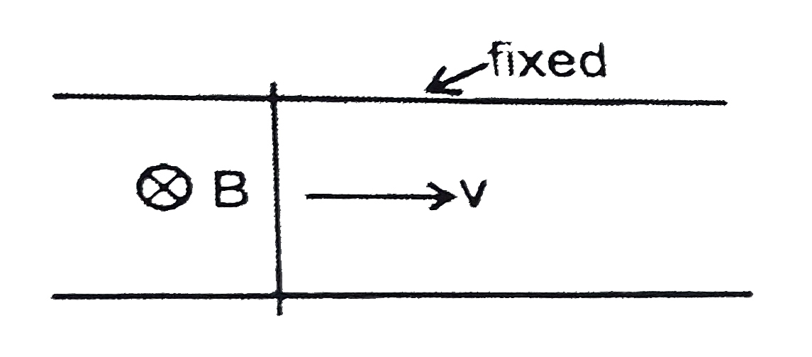
Figure shows a wire of resistance R sliding on two parallel, conducting fixed thick rails placed at a separation l. A magnetic fild B exist in a direction perpendicular to the plane of the rails. The wire is moving with a constant velocity v. Find current through the wire
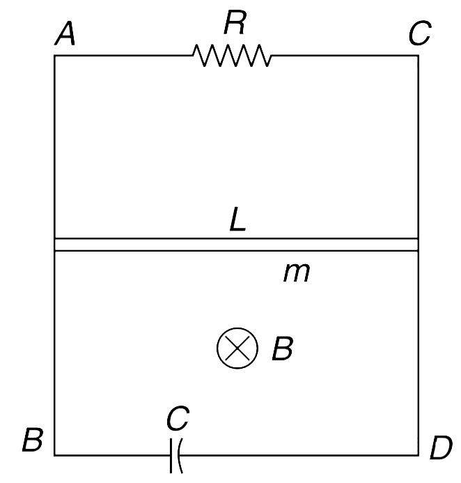
View SolutionTwo long fixed parallel vertical conducting rails AB and CD are separated by a distance L. They are connected by resistance R and a capacitance C at two ends as shown in the figure. There is a uniform magnetic field B directed horizon- tally into the plane of the figure. A horizontal metallic bar of length L and mass m can slide without friction along the rails. The bar is released from rest at t = 0. Neglect resistance of bar and rails and also neglect the self inductance of the loop.
(a) Find the maximum speed acquired by the bar after it is released.
(b) Find the speed of the bar as a function of time t.
View Solution
Knowledge Check
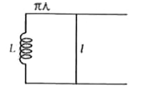
Two parallel resistanceless rails are connected by an inductor or inductance L at one end as shown in figure. A magnetic field B exists in the space which is perpendicular to the plane of the rails. Now a conductor of length l and mass m is placed transverse on the rail and given an impulse J towards the rightward direction. Then select the corrent option(s).
 Avelocity of the conductor is half of the initial velocity after a displacement of the conductor d=√3J2L4B2l2mBvelocity of the conductor is half of the initial velocity after a displacement of the conductor d=√3J2LB2l2mCcurrent flowing through the inductor at the instant when velocity of the conductor is half of the initial velocity is i=√3J24LmDcurrent flowing through the inductor at the instant when velocity of the conductor is half of the initial velocity is i=√3J2mL
Figure shows a wire sliding on two parallel, conducting rails placed at a separation L . A magnetic field B exists in a direction perpendicular to the plane of the rails. What force is necessary to keep the wire moving at a constant velocity V ?
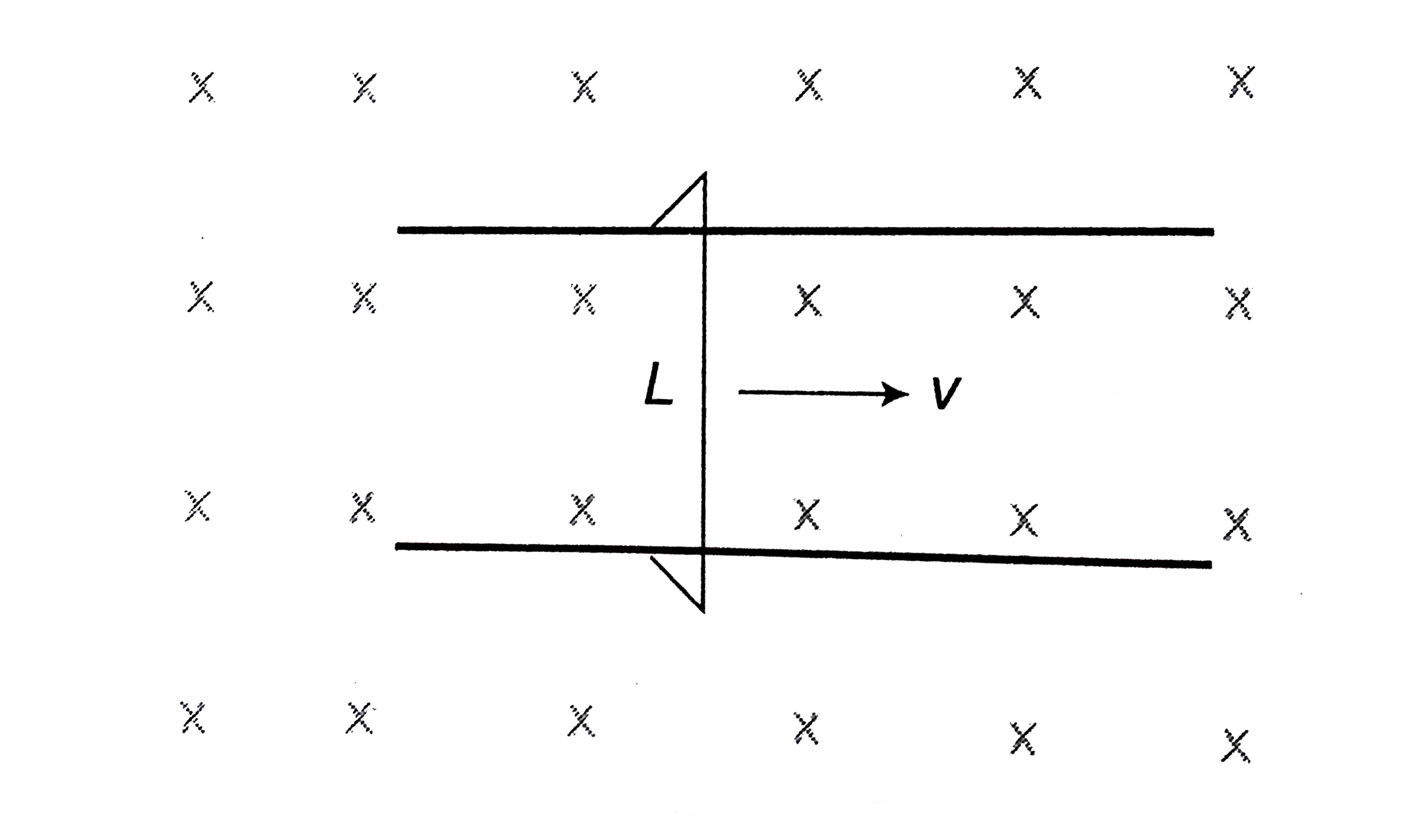 ABvLBBv2LCzeroDB2v2L/R
A copper wire ab of length l, resistance r and mass m start sliding at t=0 down a smooth, vertical, thick pair of connected conducting rails as shown in figure. A uniform magnetic field B exists in the space in a direction perpendicular to the plane of the rails which options are correct .
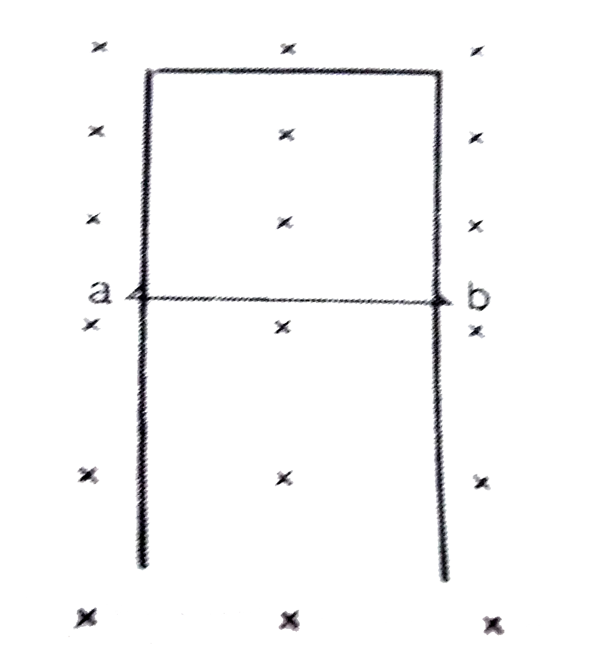 AThe magnitude and direction of the induced current in the wire when speed of the wire v is vBlr, a to bBThe downward acceleration of the wire at this instant g−B2l2mrvCThe velocity of the wire as a function of time vm(1−e−gt/vm),(wherevm=mgrB2l2)DThe displacement of the wire as a function of time vmt−v2mg(1−e−gt/vm),(wherevm=mgrB2l2)
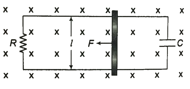
Two parallel long smooth conducting rails separated by a distance l are connected by a movable conducting connector of mass m. Terminals of the rails are connected by the resistor R and the capacitor C as shown in figure. A uniform magnetic field B perpendicular to the plane of the rail is switched on. The connector is dragged by a constant force F. Find the speed of the connector as a function of time if the force F is applied at t=0. Also find the terminal velocity of the connector.
View Solution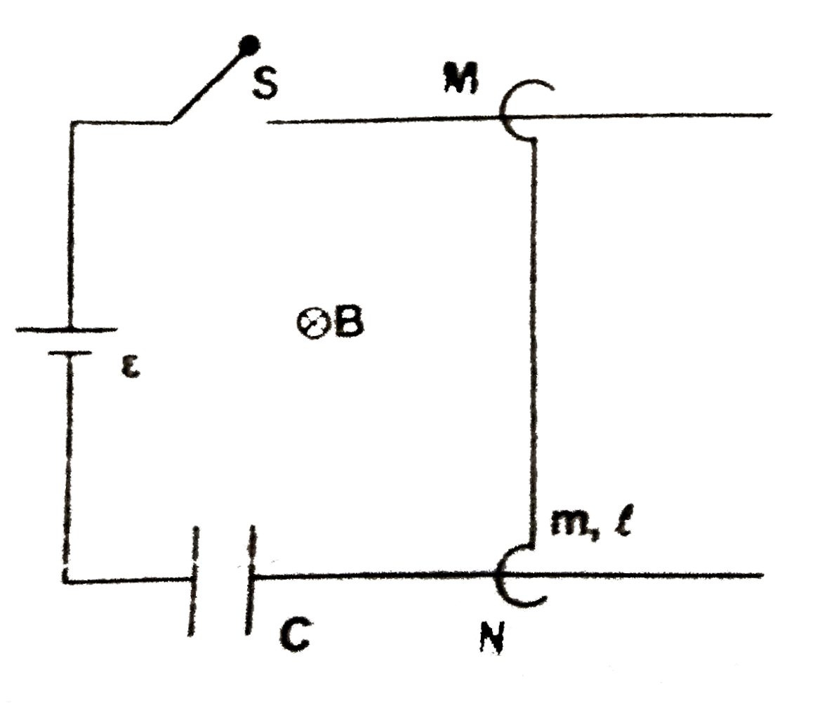
A conducting rod MN of mass m and length 'l' is placed on parallel smooth conducting rails connected to an uncharged capacitor of capacitance C and a battery of emf ε as shown. A uniform magnetic field B is existing perpendicular to the plane of the rails. The steady state velocity acquired by the conducting rod MN after closing switch S is (neglect the resistance of the parallel rails and the conducting rod)
View SolutionA conducting wire xy of lentgh l and mass m is sliding without friction on vertical conduction rails ab and cd as shown in figure. A uniform magnetic field B exists perpendicular to the plane of the rails, x moves with a constant velocity of
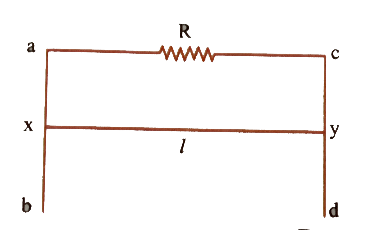
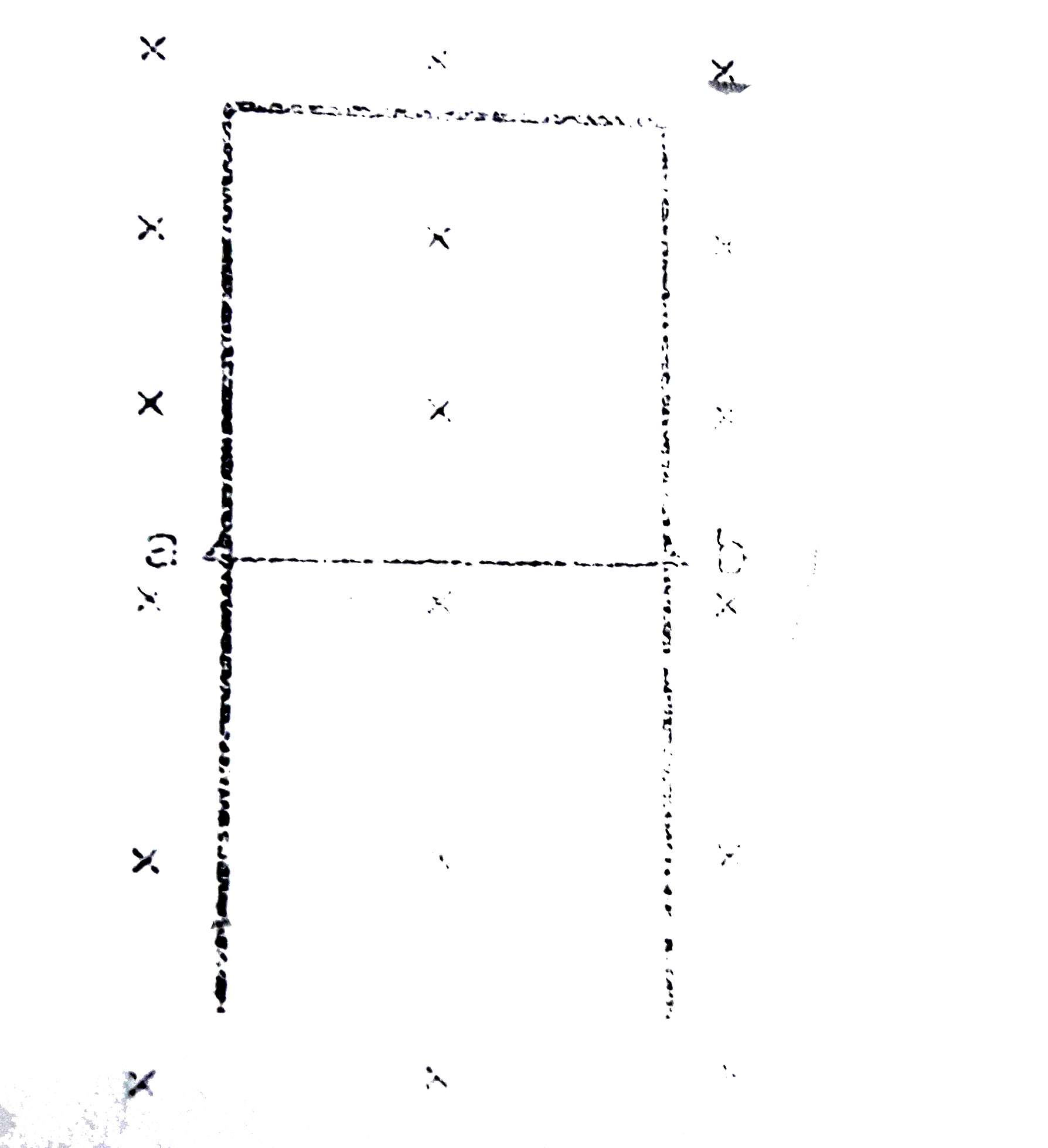
View SolutionA copper wire ab of length l, resistance r and mass m starts sliding at t=0 down a smooth, vertical, thick pair of connected condcuting rails as shown in figure.A uniform magnetic field B exists in the space in a direction perpendicular to the plane of the rails which options are correct.
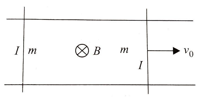
View SolutionConsider parallel conducting rails separated by a distance l. There exists a uniform magnetic field B perpendicular to the plane of the rails as shown in Fig. Two conducting wires each of length l are placed so as to slide on parallel conducting rails. One of the wires is given a velocity v0 parallel to the rails. Till steady state is achieved, loss in kinetic energy of the system is
View Solution
