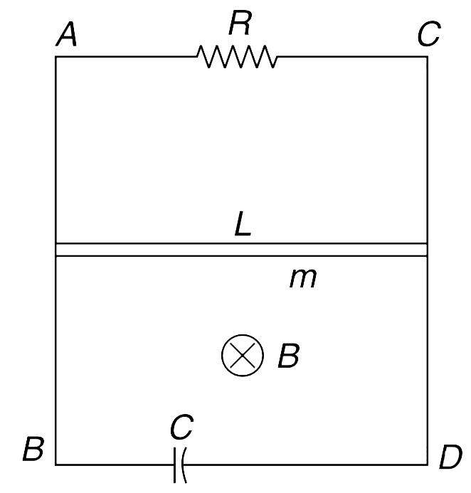
Two long fixed parallel vertical conducting rails AB and CD are separated by a distance L. They are connected by resistance R and a capacitance C at two ends as shown in the figure. There is a uniform magnetic field B directed horizon- tally into the plane of the figure. A horizontal metallic bar of length L and mass m can slide without friction along the rails. The bar is released from rest at t = 0. Neglect resistance of bar and rails and also neglect the self inductance of the loop.
(a) Find the maximum speed acquired by the bar after it is released.
(b) Find the speed of the bar as a function of time t.
The correct Answer is:(a) mgRB2L2
(b) v=mgRB2L2⎡⎢⎣1−e−B2L2tR(m+B2L2C)⎤⎥⎦
Step by step video, text & image solution for Two long fixed parallel vertical conducting rails AB and CD are separated by a distance L. They are connected by resistance R and a capacitance C at two ends as shown in the figure. There is a uniform magnetic field B directed horizon- tally into the plane of the figure. A horizontal metallic bar of length L and mass m can slide without friction along the rails. The bar is released from rest at t = 0. Neglect resistance of bar and rails and also neglect the self inductance of the loop. (a) Find the maximum speed acquired by the bar after it is released. (b) Find the speed of the bar as a function of time t. by Physics experts to help you in doubts & scoring excellent marks in Class 12 exams.
Updated on:21/07/2023Topper's Solved these Questions
- ELECTROMAGNETIC INDUCTIONBOOK - ARIHANTCHAPTER - ELECTROMAGNETIC INDUCTIONEXERCISE - Level 3
12 Videos
- ELECTROMAGNETIC INDUCTIONBOOK - ARIHANTCHAPTER - ELECTROMAGNETIC INDUCTIONEXERCISE - Level 3
12 Videos
- CURRENT ELECTRICITYBOOK - ARIHANTCHAPTER - CURRENT ELECTRICITYEXERCISE - Current Electricity
105 Videos
- ELECTROSTATICSBOOK - ARIHANTCHAPTER - ELECTROSTATICSEXERCISE - Level 3
59 Videos
Similar Questions
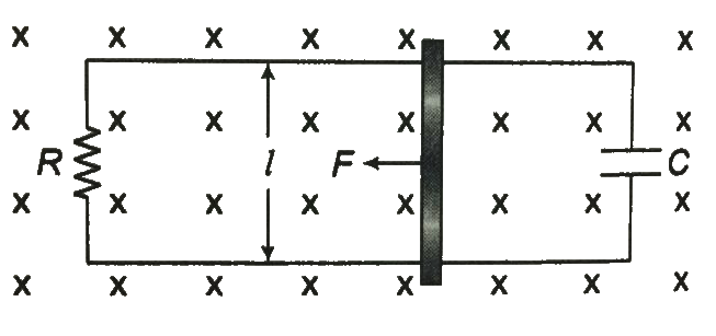
Two parallel long smooth conducting rails separated by a distance l are connected by a movable conducting connector of mass m. Terminals of the rails are connected by the resistor R and the capacitor C as shown in figure. A uniform magnetic field B perpendicular to the plane of the rail is switched on. The connector is dragged by a constant force F. Find the speed of the connector as a function of time if the force F is applied at t=0. Also find the terminal velocity of the connector.
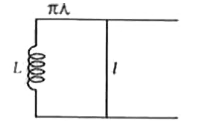
View SolutionTwo parallel resistanceless rails are connected by an inductor or inductance L at one end as shown in figure. A magnetic field B exists in the space which is perpendicular to the plane of the rails. Now a conductor of length l and mass m is placed transverse on the rail and given an impulse J towards the rightward direction. Then select the corrent option(s).
View Solution
Knowledge Check
A conducting wire of length l and mass m can slide without friction on two parallel rails and is connected to capacitance C. Whole system lies in a magnetic field B and a constant force F is applied to the rod. Then
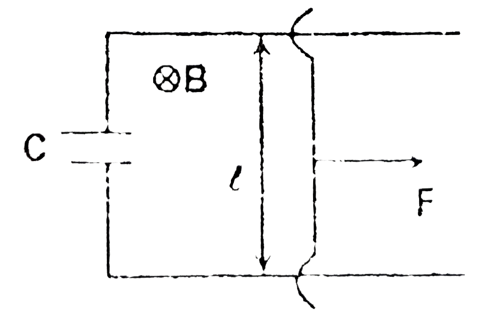 Athe rod moves with constant velocityBthe rod moves with an acceleration of Fm+B2l2cCthere is constant charge on the capacitor.Dcharge on the capacitor increases with time
A conducting wire of length l and mass m can slide without friction on two parallel rails and is connected to capacitance C. The whole system lies in a magnetic field B and a constant force F is applied to the rod. Then
Athe rod moves with constant velocityBthe rod moves with an acceleration of Fm+B2l2CCthere is constant charge on the capacitor.Dcharge on the capacitor increases with timeA conducting wire of length l and mass m can slide without friction on two parallel rails and is connected to capacitance C. The whole system lies in amagnetic field B and a constant force F is applied to the rod . Then
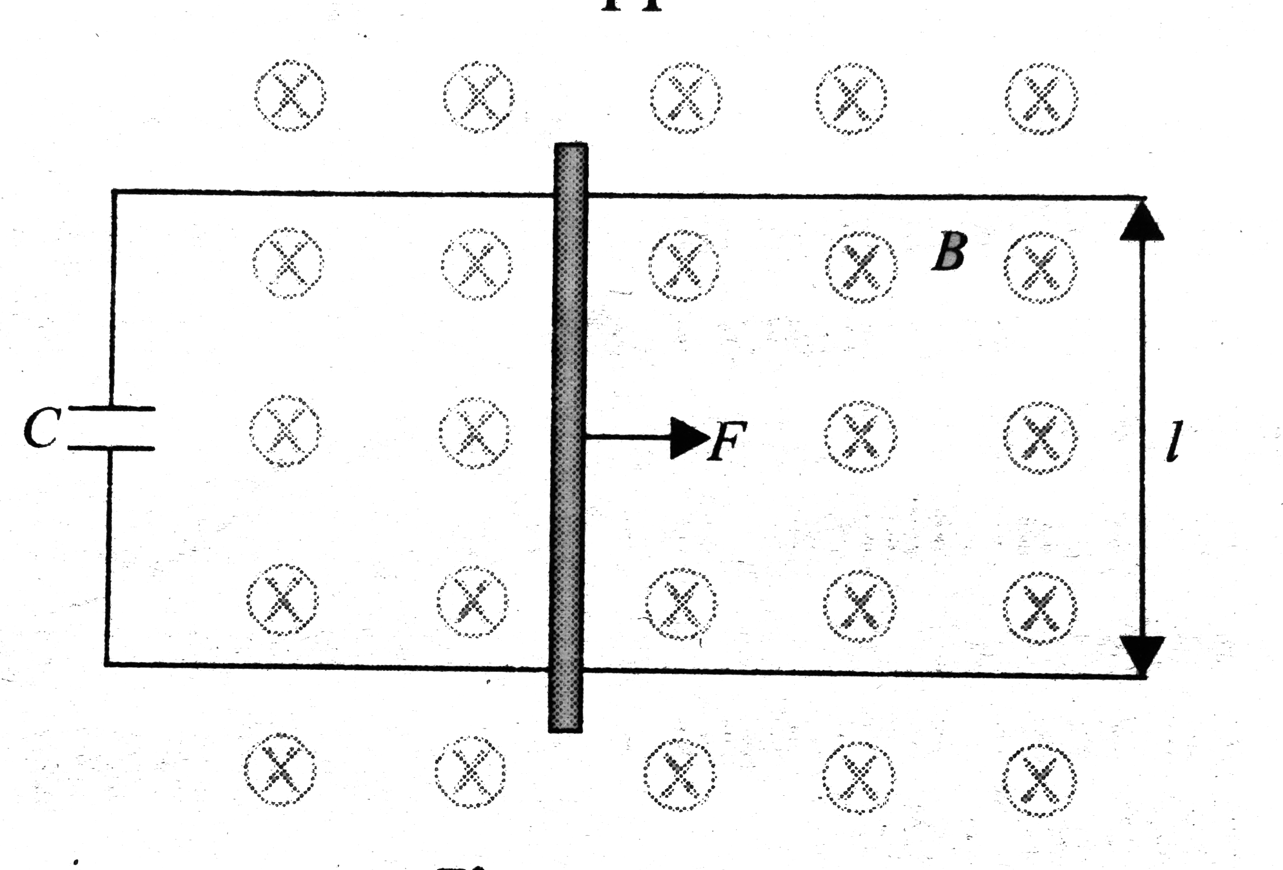 A(a) the rod moves with constant velocity.B(b) the rod moves with an acceleration of (F)/(m+B2l2C).C(c ) there is constant charge on the capacitor.D(d) charge on the capacitor increases with time.
Two parallel vertical metallic rails AB and CD are separated by 1m. They are connected at the two ends by resistances R1 and R2 as shown in the figure. A horizontal metallic bar l of mass 0.2kg slides without friction, vertically down the rails under the action of gravity. There is a uniform horizontal magnetic field of 0.6T perpendicular to the plane of the rails. It is observed that when the terminal velocity is attained, the powers dissipated in R1 and R2 are 0.76W and 1.2W respectively (g=9.8m/s2)
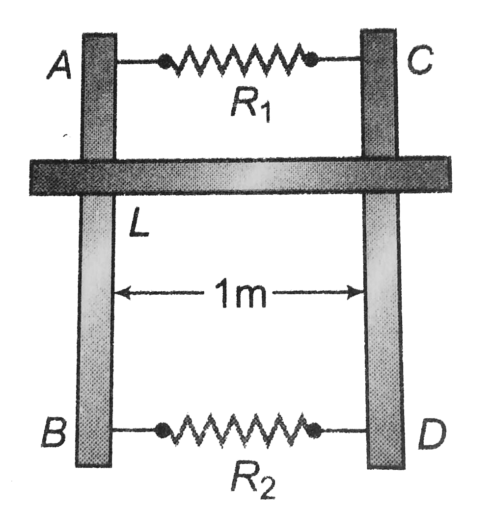
The value of R1 is
View SolutionTwo parallel vertical metallic rails AB and CD are separated by 1m. They are connected at the two ends by resistances R1 and R2 as shown in the figure. A horizontal metallic bar l of mass 0.2kg slides without friction, vertically down the rails under the action of gravity. There is a uniform horizontal magnetic field of 0.6T perpendicular to the plane of the rails. It is observed that when the terminal velocity is attained, the powers dissipated in R1 and R2 are 0.76W and 1.2W respectively (g=9.8m/s2)
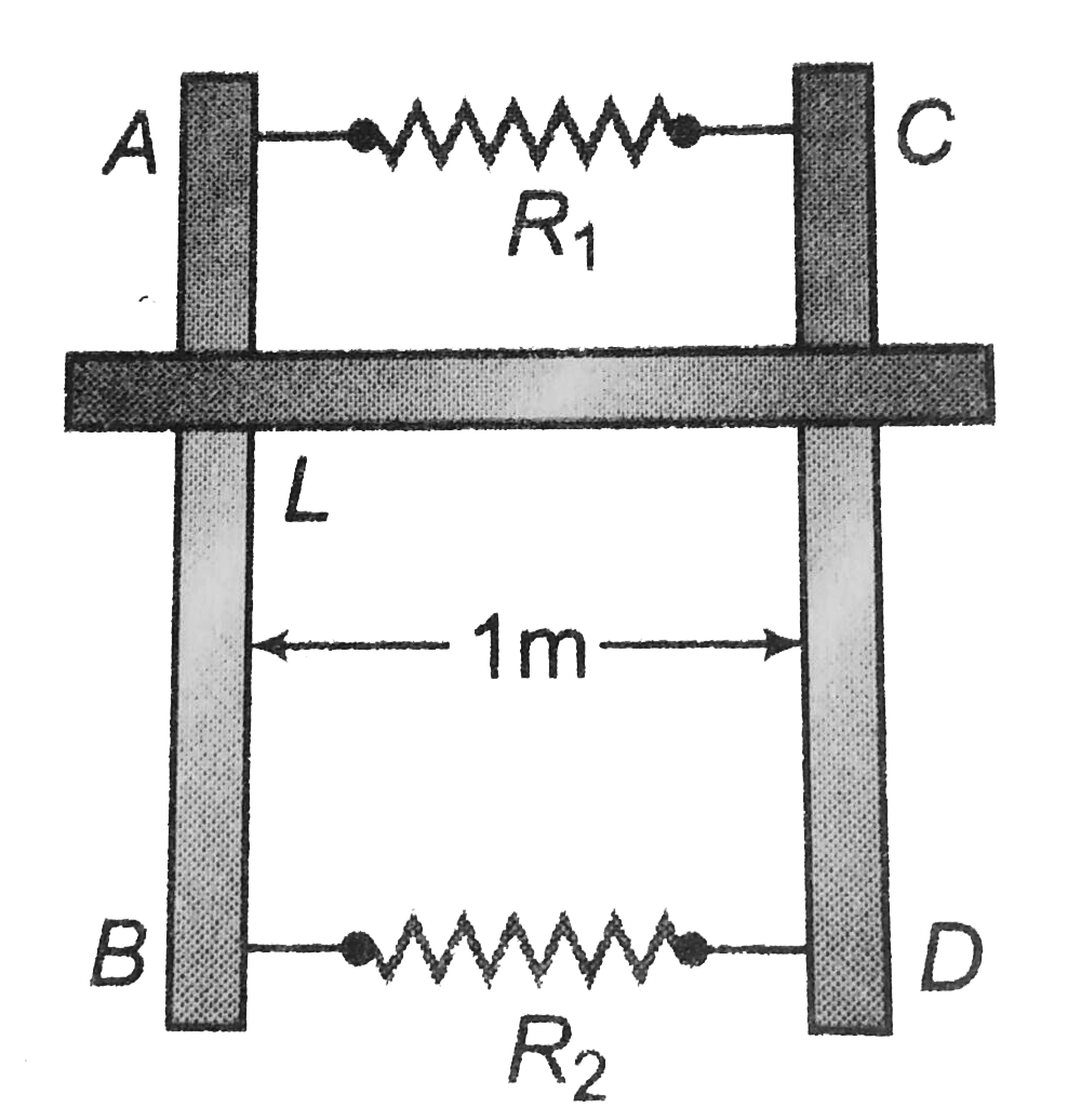
The value of R2is
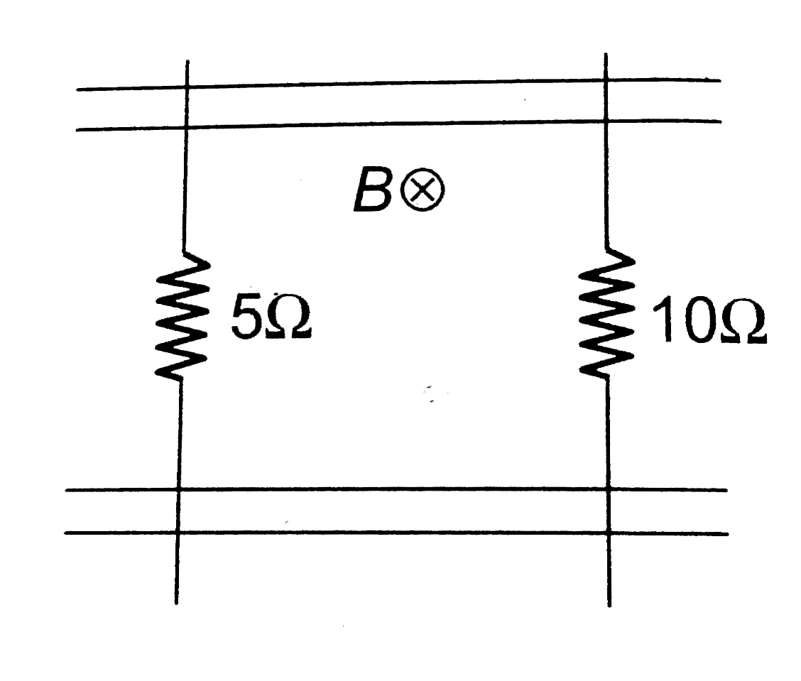
View SolutionA pair of parallel conducting rails lie at right angle to a uniform magnetic field of 2.0T as shown in the fig. two resistor 10Ω and 5Ω are to slide without friction along the rail. The distance between the conducting rails is 0.1m. Then
View SolutionTwo parallel vertical metallic rails AB and CD are separated by 1m. They are connected at the two ends by resistances R1 and R2 as shown in the figure. A horizontal metallic bar l of mass 0.2kg slides without friction, vertically down the rails under the action of gravity. There is a uniform horizontal magnetic field of 0.6T perpendicular to the plane of the rails. It is observed that when the terminal velocity is attained, the powers dissipated in R1 and R2 are 0.76W and 1.2W respectively (g=9.8m/s2)
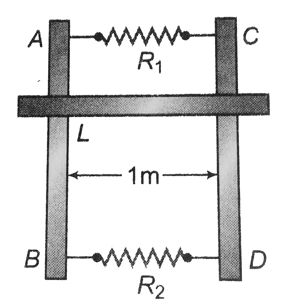
The terminal velocity fo the bar L will be
View SolutionA copper rod of mass m slides under gravity on two smooth parallel rails l distance apart set at an angle θ to the horizontal. At the bottom, the rails are joined by a resistance R.
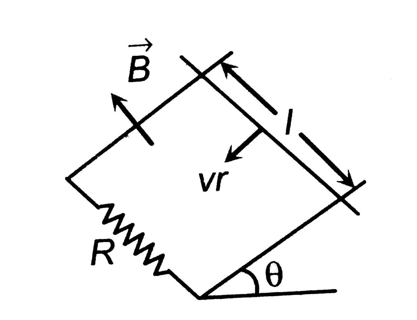
There is a uniform magnetic field perpendicular to the plane of the rails. the terminal valocity of the rod is
View Solution
