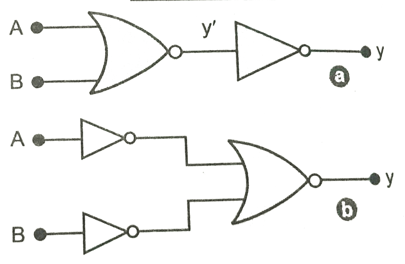
You are given the two circuits as shown in Fig. and . Show that circuit acts as OR gate while the circuit acts as AND gate.
Video Solution
Text Solution
(a) A and B are the inputs and Y is the output of the given circuit. The left half of the given figure acts as the NOR Gate, while the right half acts as the NOT Gate. This is shown in the following figure. 
Hence, the output of the NOR Gate =¯¯¯¯¯¯¯¯¯¯¯A+B
This will be the input for the NOT Gate. Its output will be =¯¯¯¯¯¯¯¯¯¯¯¯¯¯¯¯¯¯¯¯¯¯A+B=A+B
∴Y=A+B
Hence, this circuit functions as an OR Gate.
(b) A and B are the inputs and Y is the output of the given circuit. It can be observed from the following figure that the inputs of the right half NOR Gate are the outputs of the two NOT Gates.
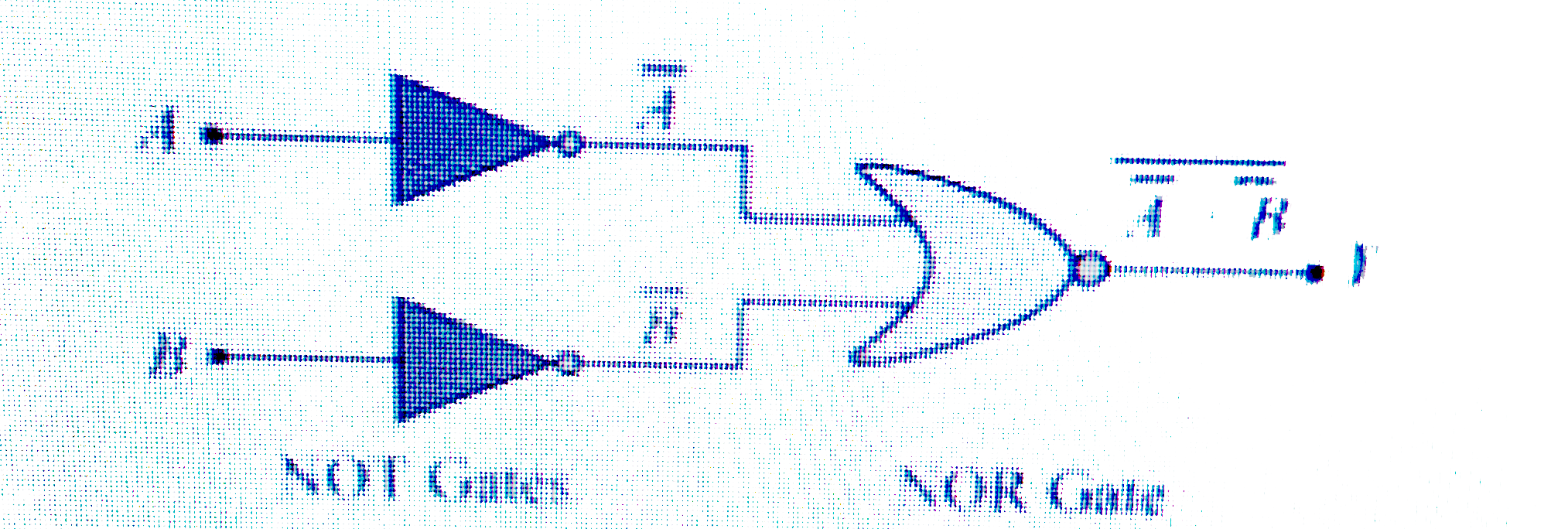
Hence, the output of the given circuit can be written as:
Y=¯¯¯¯¯¯¯¯¯¯¯¯¯¯¯A+¯¯¯B=¯¯¯¯¯¯¯A+¯¯¯¯¯¯B=A.B
Hence, this circuit functions as an AND Gate.
|
Updated on:21/07/2023
Topper's Solved these Questions
- BOOK - NCERT ENGLISHCHAPTER - SEMICONDUCTOR ELECTRONICS MATERIALS DEVICES AND SIMPLE CIRCUITSEXERCISE - Exercise15videos
SEMICONDUCTOR ELECTRONICS MATERIALS DEVICES AND SIMPLE CIRCUITS
- BOOK - NCERT ENGLISHCHAPTER - RAY OPTICS AND OPTICAL INSTRUMENTSEXERCISE - Exercise32videos
RAY OPTICS AND OPTICAL INSTRUMENTS
- BOOK - NCERT ENGLISHCHAPTER - WAVE OPTICS EXERCISE - Exercise21videos
WAVE OPTICS
Similar Questions
In the two circuits shown in figure
 View Solution
In the circuit shown in Fig. 7.45,
 View Solution
For the circuit shown
 View Solution
In the given circuit (as shown in fig. 5.319).
 View Solution
In the circuit shown
 View Solution
In the given circuit (as shown in the figure)View SolutionThe circuit shown in the figure acts as
 View Solution
In the circuit shown in figure current in the circuit is
 View Solution
In the transient circuit shown, the time constant of the circuit is :
 View Solution
You are given two circuits as shown in following figure. The logic operation carried out by the two circuit are respectively :-
_E01_415_Q01.png) View Solution
View Solution

