In the circuit shown
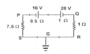
A
the potential at Πs−7.5V
B
the potential at Qis−1V
C
the potential at R is zero
D
the potential al S is zero
Video Solution
Text Solution
The current in the circuitI=20−107.5+0.5+1+1=1010=1amp
The potential difference across PS,Vps=7.5×1=7.5V
The potential difference across Q, R, VQR=1×1=1V
As point G is connected to earth, hence potentials of R and Sare zero. The direction of the current in the circuit is from P to S, hence point P is at higher potential
thereforeVp=7.5V,
Similarly, VQ=−1V
Hence, (B) (C) & (D) are correct.
|
Updated on:21/07/2023
Similar Questions
In the circuits shown below, the readings of the voltmeters and the ammeters will be:
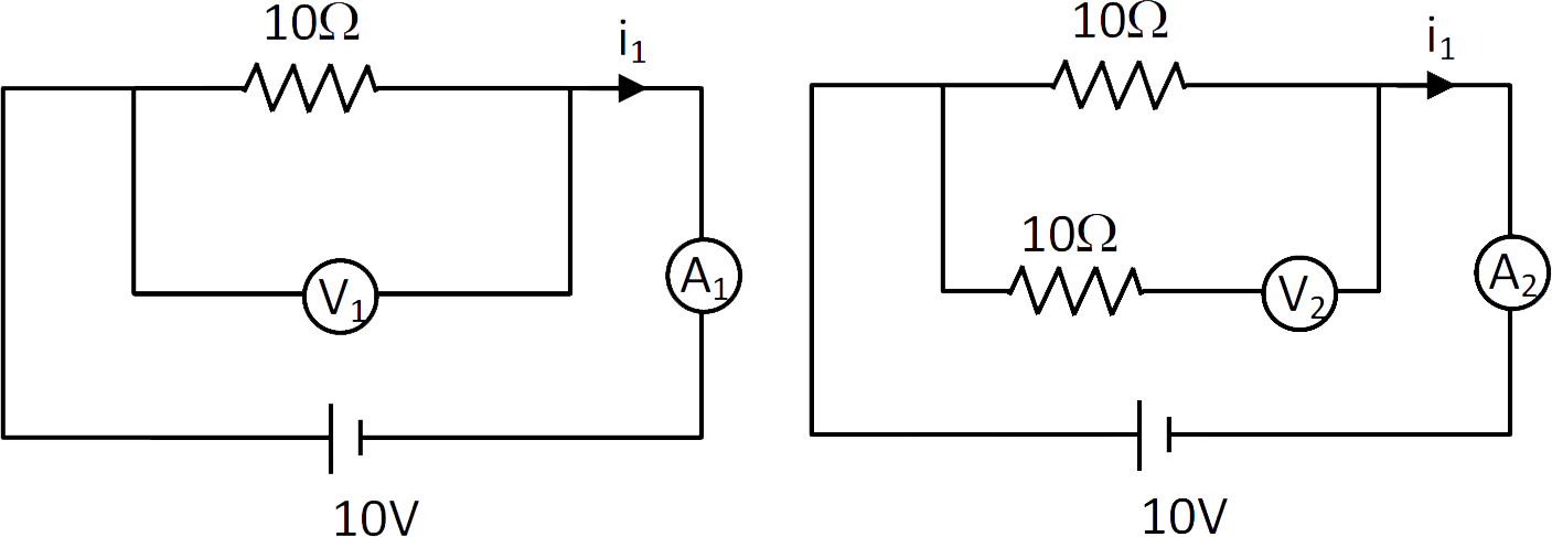 View Solution
For the circuit shown in figure,
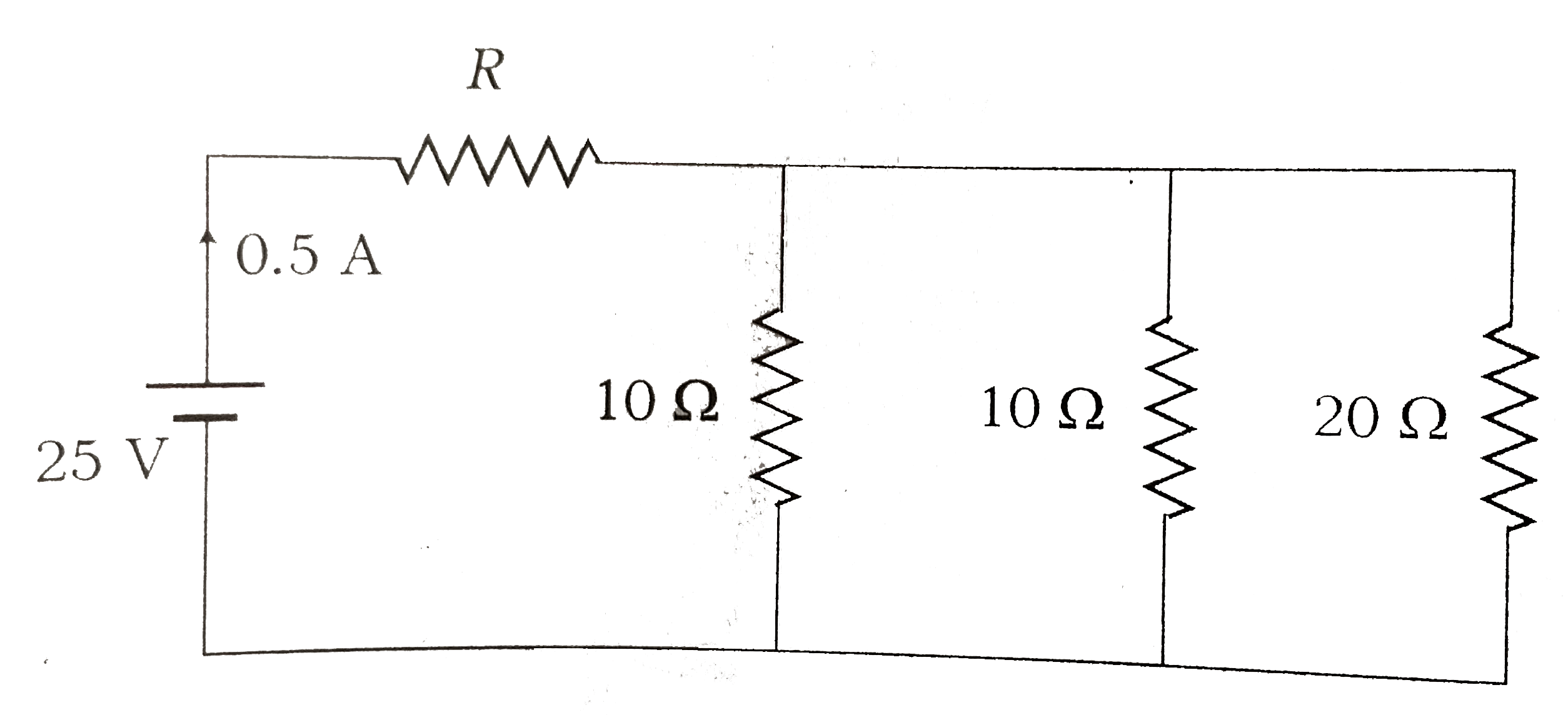 View Solution
Impendance of the circuit shown in the figure is
 View Solution
For the circuit shown in figure
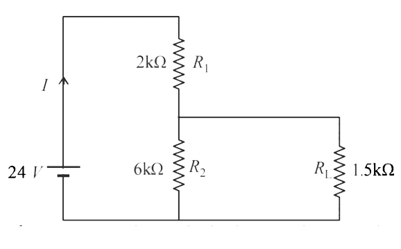 View Solution
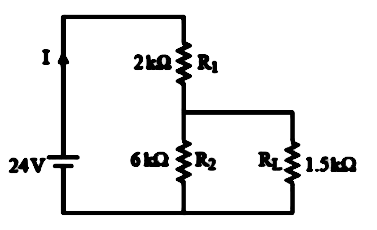
For the circuit shown in the figure
 View Solution
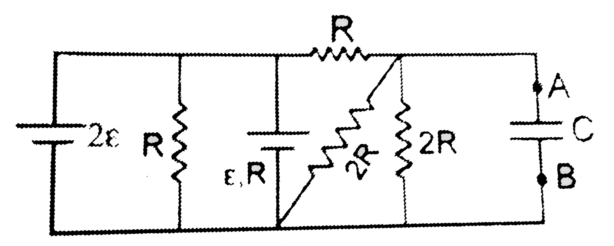
The time constant of the circuit shown is :
 View Solution
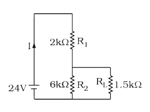
For the circuit shown in the figure
 View Solution
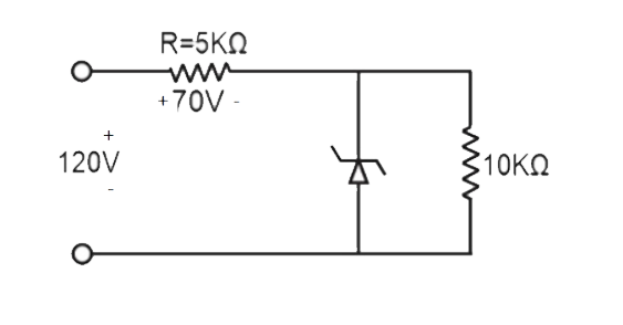
For the circuit shown in the figure :
 View Solution
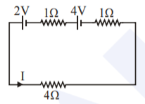
For the circuit shown in the figure current I will be
 View Solution
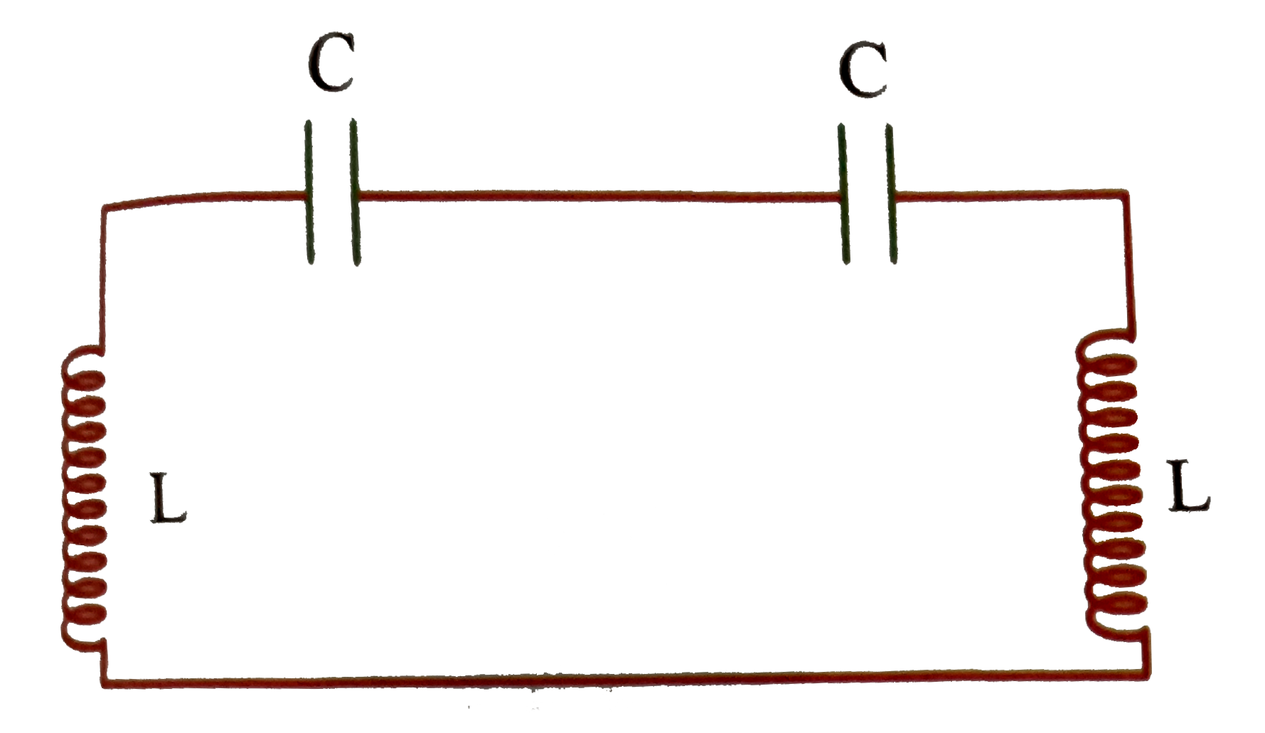
The natural frequency of the circuit shown in the figure is
 View Solution

